TME-104P-CSR-LX800-R1V5.doc
Rev 1.5
16 (44)
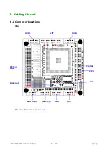
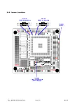
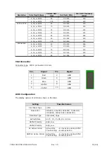
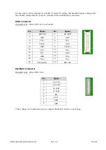
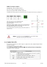
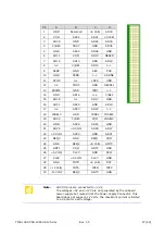
Display Voltage Jumpers
Jumper
LVDS and Backlight
Connector type: IDC6, 2.00 mm.
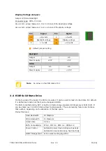
Use a 2 mm jumper between 1-3 or 3-5 to select the backlight voltage.
Use a 2 mm jumper between 2-4 or 4-6 to select the display voltage.
Pin
Signal
Pin
Signal
1 +12
volts 2 +5
volts
3 Backlight
voltage 4 Display
voltage
5
+ 5 volts
6 +3.3
volts
Backlight
Jumper 1-3
3-5
Power supply
+12V
+5V
LVDS
Jumper 2-4
4-6
Power supply
+5V
+3.3V
Note
An arrow on the PCB marks Pin 1
3.4
EIDE Solid State Drive
On the top side of the board, the SSD is mounted. It can be used instead of a hard disk. Per default,
it is defined as master but that can be changed in BIOS.
The SSD, manufactured by SST, is built as a flash storage organized of Single Level Cells (SLC). It
can be erased over 100.000 times without losing capacity. The wear-leveling feature can increase
that number, depending on the allocation of the disk space.
Product features:
Read Bandwidth
30 Mbytes/s
Write Bandwidth
10 Mbytes/s
Access time
0.2 ms
PATA Compatibility
ATA-5; PIO 0-4; DMA 0-2; UDMA 0-4
Power Control
Automatic power down during wait periods
Automatic sleep mode during host inactivity
NAND Management Active wear-leveling algorithm
default jumper setting


