– –
– –
14
15
8. The Status Details section shows the module’s control line states, radio
state and RSSI level.
9. The Sent and Received Packets window shows the commands
sent to the module and the responses from the module. This aids in
debugging custom software.
10. Once a module has been configured, the configurations can be saved
into a profile that can be recalled and programmed into other modules.
The Saved Profiles list shows all of the profiles that have been saved
into the software.
11. The Show Commands button opens a larger window to view the serial
commands sent to and received from the module.
The modules are shown with three identifiers as shown in Figure 14.
1. The type of module (TT Series)
2. The module’s local address.
3. A custom name that can be given to the module. Type a name into
the box and press Enter to apply it. This name is shown on the LCD
display on the programming dock.
Figure 14: The Master Development System
Software Module Identifiers
1
2
3
Figure 15: The Master Development System
Software Additional Information
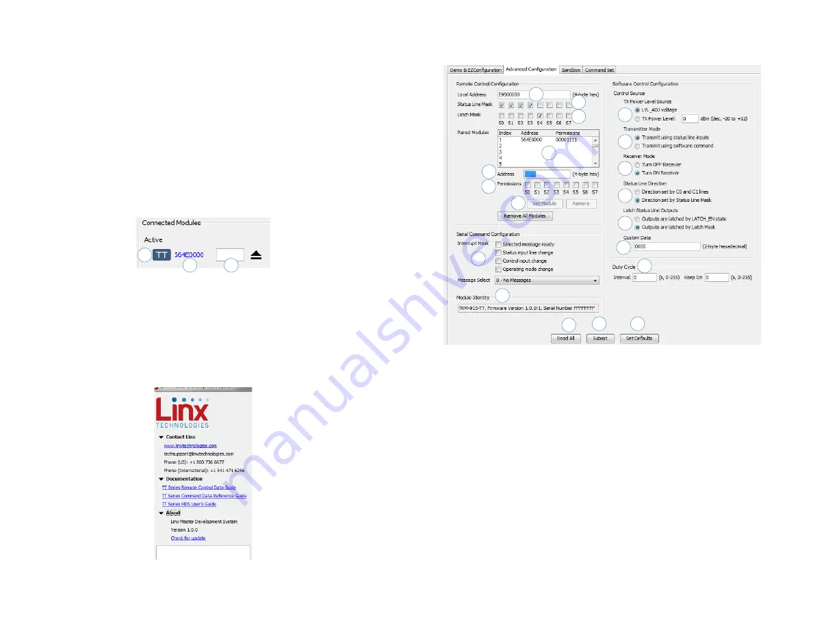
The Advanced Configuration tab (Figure 16) offers more detailed
configuration options for the active module.
1. The Local Address box shows the module’s local address in
hexadecimal format. This can be changed by typing a new hex value.
2. The Status Line Mask sets the status lines as either inputs or outputs.
If the box is checked then the line is an input.
3. The Latch Mask determines if the status line outputs are latched or
momentary. If the box is checked then the output is latched. This
setting has no effect on lines that are configured as inputs.
4. The Paired Modules Window lists all of the modules that are paired
with the active module and their Permissions Mask.
5. The Address box enables manual pairing of a module. Enter an
address into this box and press the Set Module button to add the
address to the list.
6. The Permissions Mask determines whether a specific module is
authorized to control a specific status line output. If the box is checked
then the module is authorized to control that line.
Figure 16: The Master Development System Software Advanced Configuration Tab
7
4
1
2
3
10
6
8
11
5
9
12
13
14
16
17
18
15
19


