


20
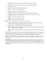
•
Value
- These are Min/Max values used for the display. This is useful for preventing a Meter from going past its end or
setting the value of a VBar. This is the Value after the Corrector. The system cannot display a value past Max so be sure this
is at least set to 1.
•
Yellow/Red/Green
- There are three colors that can be used to further define a display. Set the range of these colors to
define a color to the display Value. This is the Value after the Corrector. Note that if you are using a State type you may
want to assign RED = From 0 to 0, GREEN = From 1 to 1 and YELLOW = From 2 to 2. Since a State is always either 1 or 0 this
will prevent ambiguous information and prevent the YELLOW color from being used. You can select any two colors you like
for a State type.
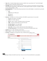
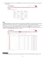
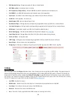
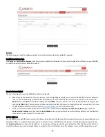
Set Analog Input
The Analog Inputs can be set to provide various readouts on using a range of display types. In addition to displaying the input data,
you can name the display as well as associate a relay with it. This relay will change from Green to RED as it goes from on to off as
well as is clickable to control it.
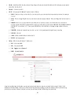
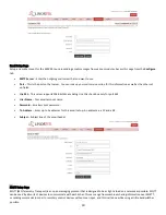
•
Analog Input Selected
- The Analog Input that you are editing is identified by the line on which you clicked the Edit icon.
•
Name
- You can set a 15-character name for this input. This name goes in the bar at the top of the display.
•
Label
- Set a 7-character label which is displayed on the actual active display.
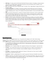
•
Corrector
- Using this field you can add, subtract, multiply, or divide a value before the value is shown on the display page.
This is a 2-value corrector with each being separated by a single space character. (ie. "+2, -2, *3, /3")
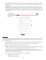
•
USE
- Sets this input to active. Turns the input number indicator to green. It should be noted that when in use the input
consumes CPU time and other resources depending on its type. Although all inputs may be active at the same time, it is
recommended to turn on only those you want to use.
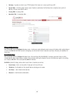
•
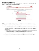
Type
- The input data can be used to calculate a range of results. You may select:
•
Analog 1
- Analog 1 input from a Ultra
•
Analog 2
- Analog 2 input from a Ultra