background image

13

7  |  Attachment

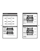
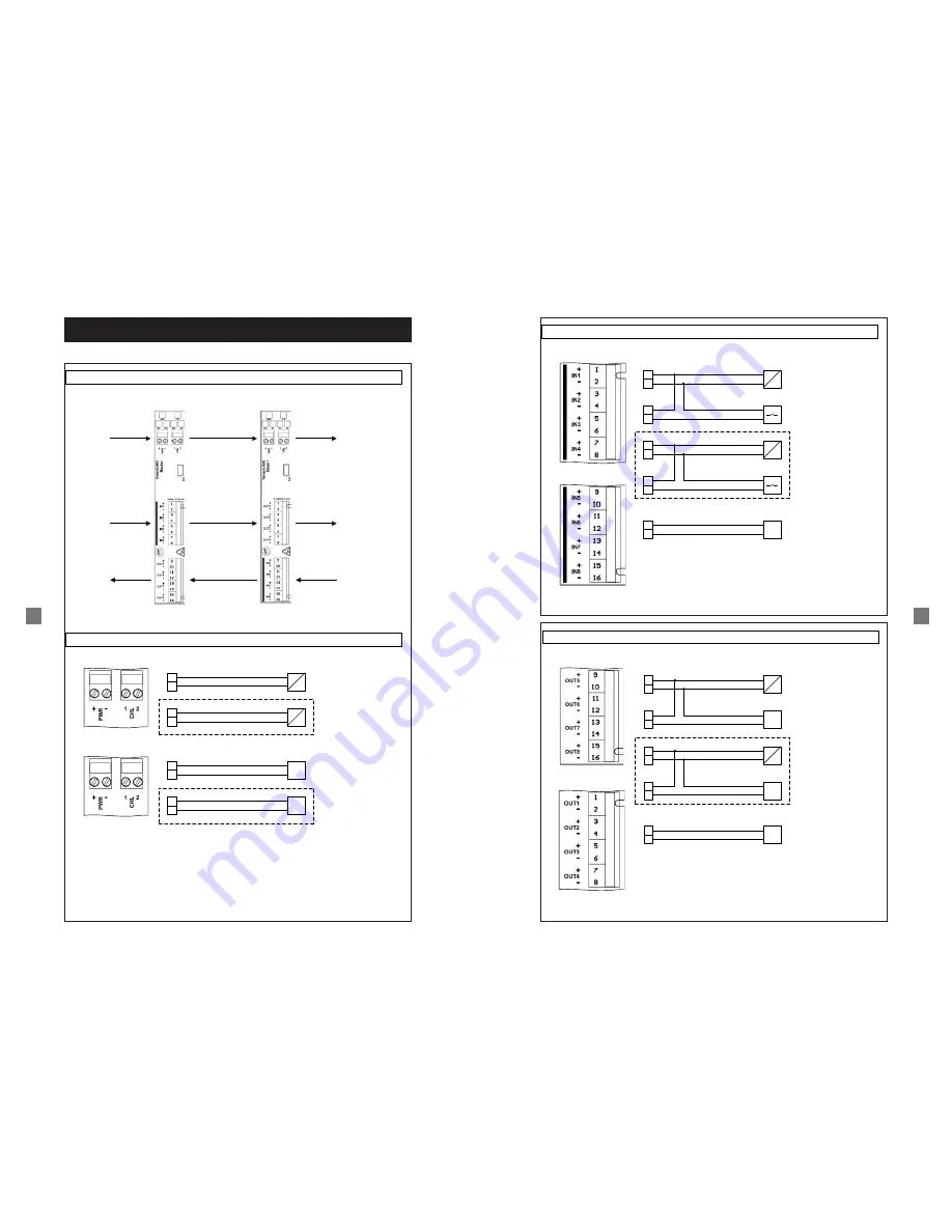
Connection example

Power supply

+

-

PWR

12V - 24V

=

Optional

1
2

CHL

=

12V - 48V

+

-

PWR

Load

Optional

1
2

CHL

Load

Note

:

The correct polarity of the voltage PWR is to be ensured! 

The CHL connection is optional and can be freely assigned.

Master:

Slave 1:

Connection example

Schematic diagramm

Control signals

Control signals

Control signals

Control signals

Voltage

Voltage

14

+

-

PWR

12V - 24V

=

+

-

IN

Signal

 transmitter

+

-

CHL

12V - 48V

=

+

-

IN

Signal transmitter

+

-

IN

Input switching 1

:

Loop through the 

voltage PWR

Connection example

Input switching (valid for the inputs IN1-8)

Master:

Slave 1:

Note

:

The correct polarity of the inputs must be ensured!

The input switching can be freely selected for each input (IN 1-8)

.

Input switching

 2:

Loop through the 

voltage

 CHL

Extern

12V - 48V

Input switching

 3: 

Applying an external 

voltage

Optional

+

-

PWR

12V - 24V

=

+

-

OUT

Load

+

-

CHL

12V - 48V

=

+

-

OUT

Load

+

-

OUT

Output switching

 1: 

Loop through the 

voltage PWR

Connection example

Output switching (valid for outputs OUT1-8)

Master:

Slave 1:

Note

:

The correct polarity of the outputs is to be ensured!

The output switching can be freely selected for each output (IN 1-8).

Output switching

 2: 

Loop through the 

voltage CHL

Extern

12V - 48V

Output switching

 3: 

Loop through an 

external voltage

Optional

Содержание SmartLINK M 13 25

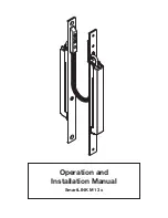
Страница 1: ...Operation and Installation Manual SmartLINK M 13 x...

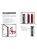
Страница 2: ...n 3 2 1 Type code 3 2 2 Terms and conditions and use 3 2 3 Technical data 3 3 Assembly 5 3 1 General notes on assembly 5 3 2 General notes on electrical connection 10 4 Commissioning and Maintenance 1...

Страница 3: ...l functioning It may be used only in accordance with the following versions or for applications approved by the installer Detailed information on the ap plication range can be found in the chapter Pro...

Страница 4: ...and its construction the domestic and commercial doors can be completely manufactured in the workshop tested as an assembly and accepted in the object immediately after installation 2 3 Technical dat...

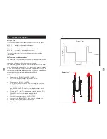
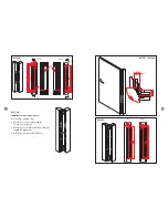
Страница 5: ...everal dimensions Please check the place of installation and the space available in the rabbet and profile area before the beginning of assembly Place of assembly Door rabbet Minimum installation dept...

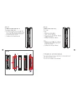
Страница 6: ...frame leaf Mill recess for lock plates radius 10 mm 3 mm deep Mill recess of 19 mm width and 268 mm length 28 mm deep Drill holes for cable exit 16 mm 20 19 268 8 16 280 300 3 28 268 280 8 16 3 28 Fl...

Страница 7: ...2 General notes on electrical connection The electrical connection may only be done in de energised state and by authorised personnel For connection examples see attachment 10 20 268 16 280 50 268 28...

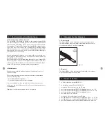
Страница 8: ...onal test is undertaken with the following steps Check SmartLINK for tightness Check lead spring and housing for damage It is recommended to clean exposed parts at least once per year with a soft dry...

Страница 9: ...ut switching valid for the inputs IN1 8 Master Slave 1 Note The correct polarity of the inputs must be ensured The input switching can be freely selected for each input IN 1 8 Input switching 2 Loop t...

Страница 10: ...15 8 1 EC Declaration of Conformity 8 Declaration of Conformity 16...

Страница 11: ...LINK GmbH D 35510 Butzbach Telephon 49 0 6033 97404 0 Fax 49 0 6033 97404 20 E Mail info link gmbh com Internet www link gmbh com Specifications subject to change without notice MA0002062 Stand 4416...

Отзывы: