background image

1

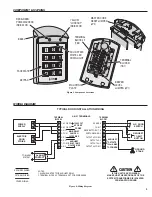
COMPONENT LOCATIONS

WIRING DIAGRAM

228045 A     IMAGE 3

RED/GREEN
POWER/ACCE

SS

INDICATOR

YELLOW
"LOCKOUT"
INDICATOR

KEYPAD

S

OLID 

S

TATE

WHITE LED
DOWN LIGHT

MA

S

TER CODE

RE

S

ET JUMPER

(JP2)

TERMINAL
BLOCK #1
(TB1)

TERMINAL
BLOCK #2
(TB2)

BEEPER
LEVEL
JUMPER (JP1)

FACEPLATE

BEZEL

MOUNTING
PLATE

1 - AC OR DC

2 - AC OR DC

3

 - N.O.

4 - COM

5 - N.C.

6 - N.O.

7 - COM

8

 - N.C.

S

EN

S

E - 

8

COM - 7

REQUE

S

T-TO-EXIT - 6

EARTH GROUND - 5

OUTPUT #

3

 COM - 4

OUTPUT #

3

 - 

3

OUTPUT #4 - 2

OUTPUT #4 COM - 1

12-24 VOLT

AC OR DC

POWER

MAIN RELAY

5 AMP

S

 @

28 VDC MAX.

AUXILIARY

RELAY 1 AMP

@ 28 VDC MAX.

TERMINAL

BLOCK 2

TERMINAL

BLOCK 1

AK-21 TERMINALS

CAUTION

IF THE UNIT IS AC POWERED,

MAKE SURE THE SECONDARY OF THE

SYSTEM TRANSFORMER IS ISOLATED

FROM EARTH GROUND

OPTIONAL WIRING

REQUIRED WIRING

OTHER WIRING

NOTE

S

1. ALARM 

S

HUNT 

S

ET FOR AUXILIARY RELAY

2. TERMINAL BLOCK #2, TERMINAL 

8


S

ET FOR DOOR 

S

EN

S

E

GROUND

STAKE

N.C. DOOR

SWITCH

ALARM

CONTACT

TO ALARM

S

Y

S

TEM

POWER
SUPPLY

ELECTRIC

DOOR

STRIKE

AUXILIARY

OUTPUT

S

100 mA MAX.
TO COMMON

REQUEST

TO EXIT

BUTTON

TYPICAL DOOR INSTALLATION WIRING

Figure 1. Component Locations

Figure 2. Wiring Diagram

Содержание ACCESS AK-21

Страница 1: ...AK 21 Digital Keyless Entry System 760 438 7000 USA Canada 800 421 1587 800 392 0123 Toll Free FAX 800 468 1340 www linearcorp com Installation and Programming Instructions...

Страница 2: ...DC source Power can be obtained from the access device or a separate power supply The EEPROM memory retains all entry codes and programming even without power An internal jumper is provided to reset t...

Страница 3: ...VOLT AC OR DC POWER MAIN RELAY 5 AMPS 28 VDC MAX AUXILIARY RELAY 1 AMP 28 VDC MAX TERMINAL BLOCK 2 TERMINAL BLOCK 1 AK 21 TERMINALS CAUTION IF THE UNIT IS AC POWERED MAKE SURE THE SECONDARY OF THE SYS...

Страница 4: ...or strike or access device Install the electrical box in the wall Screw the mounting plate onto the electrical box see Figure 5 Final Keypad Installation After wiring the keypad see next page complete...

Страница 5: ...e two wires from the switch to the keypad box Connect the door switch to the keypad s SENSE terminal TB1 8 and COM terminal TB1 7 If an inhibit switch or timer is going to be used for temporarily disa...

Страница 6: ...ey is pressed during programming to clear the keypad and re enter the command Press 9 Setting Entry Code Length Default 4 digits Press 0 3 Length Length 1 6 for entry code length NOTE If the Entry Cod...

Страница 7: ...ch output activates when any keys are pressed This output is timed If toggle mode is selected for the output the timer value defaults to 2 seconds Press 1 4 Output Output Output to Activate 0 4 1 Main...

Страница 8: ...age 12 24 Volts AC or DC Current 30 mA typical 150 mA maximum Outputs Main Relay Form C 5 Amps 28 Volts maximum Auxiliary Relay Form C 1 Amp 28 Volts maximum Solid state outputs Outputs 3 4 Short to c...

Отзывы: