19
LTC1736
Minimum On-Time Considerations
Minimum on-time t
ON(MIN)
is the smallest amount of time
that the LTC1736 is capable of turning the top MOSFET on
and off again. It is determined by internal timing delays and
the gate charge required to turn on the top MOSFET. Low
duty cycle applications may approach this minimum on-
time limit and care should be taken to ensure that:
t
V
V f
ON MIN
OUT
IN
(
)
( )
<
If the duty cycle falls below what can be accommodated by
the minimum on-time, the LTC1736 will begin to skip
cycles. The output voltage will continue to be regulated,
but the ripple current and voltage will increase.
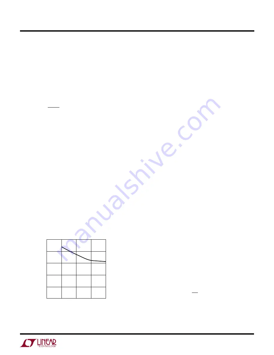
The minimum on-time for the LTC1736 in a properly
configured application is generally less than 200ns. How-
ever, as the peak sense voltage decreases, the minimum
on-time gradually increases as shown in Figure 5. This is
of particular concern in forced continuous applications
with low ripple current at light loads. If the duty cycle drops
below the minimum on-time limit in this situation, a
significant amount of cycle skipping can occur with corre-
spondingly larger current and voltage ripple.
If an application can operate close to the minimum on-
time limit, an inductor must be chosen that is low enough
in value to provide sufficient ripple amplitude to meet the
minimum on-time requirement.
As a general rule keep the
APPLICATIO S I FOR ATIO
W
U
U
U
inductor ripple current equal or greater than 30% of
I
OUT(MAX)
at V
IN(MAX)
.
FCB Pin Operation
When the DC voltage on the FCB pin drops below its 0.8V
threshold, continuous mode operation is forced. In this
case, the top and bottom MOSFETs continue to be driven
synchronously regardless of the load on the main output.
Burst Mode operation is disabled and current reversal is
allowed in the inductor.
In addition to providing a logic input to force continuous
synchronous operation and external synchronization, the
FCB pin provides a means to regulate a flyback winding
output. During continuous mode, current flows continu-
ously in the transformer primary. The secondary winding(s)
draw current only when the bottom synchronous switch is
on. When primary load currents are low and/or the
V
IN
/V
OUT
ratio is low, the synchronous switch may not be
on for a sufficient amount of time to transfer power from
the output capacitor to the secondary load. Forced con-
tinuous operation will support secondary windings pro-
vided there is sufficient synchronous switch duty factor.
Thus, the FCB input pin removes the requirement that
power must be drawn from the inductor primary in order
to extract power from the auxiliary windings. With the loop
in continuous mode, the auxiliary output may nominally be
loaded without regard to the primary output load.
The secondary output voltage V
SEC
is normally set as
shown in the Functional Diagram by the turns ratio N of the
transformer:
V
SEC
≅
(N + 1) V
OUT
However, if the controller goes into Burst Mode operation
and halts switching due to a light primary load current,
then V
SEC
will droop. An external resistive divider from
V
SEC
to the FCB pin sets a minimum voltage V
SEC(MIN)
:
V
V
R
R
SEC MIN
(
)
.
≈
+
0 8
1
4
3
If V
SEC
drops below this level, the FCB voltage forces
continuous switching operation until V
SEC
is again above
its minimum.
∆
I
L
/I
OUT(MAX)
(%)
0
MINIMUM ON-TIME (ns)
100
150
40
1736 F05
50
0
10
20
30
250
200
Figure 5. Minimum On-Time vs
∆
I
L


