background image

AERO.2000 User Guide  July 2016     


 L16/1/18039 


©2016 LINEAR ACOUSTIC INC. THE TELOS ALLIANCE. ALL RIGHTS RESERVED


Page 30 


bottom sections to be resized.  Place your pointer in the ribbed area and left click to change the 
relative sizes of the meters and controls. See Figure 6-5, above. 

In the Tabbed mode, all menus and all controls are displayed on the screen simultaneously (see 
Figure 6-6 below).  This mode inherently makes menus, controls, and their labels smaller. This 
mode works best when the remote software window can be made large enough so that all text 
items can be easily read.  In Tabbed mode you have direct access to all menus items and 
associated controls without having to step through the menu structure in sequence.   

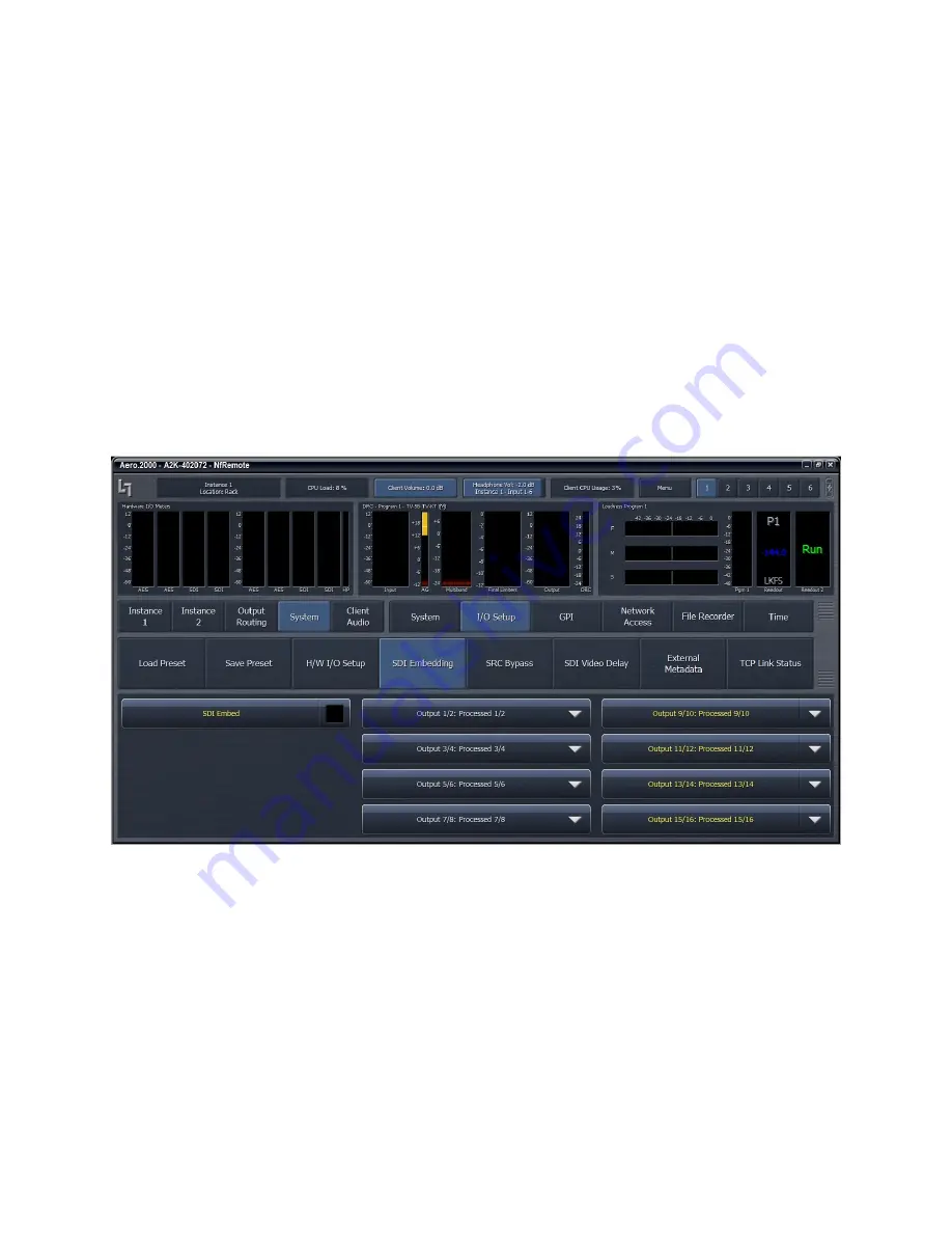
Figure 6-6 shows the same menu location as Figure 6-5 but in Tabbed view.  Notice that you can 
see all of the sub-menus of System (top row, right side), all of the sub-menus of I/O Setup in the 
center section, and all of the available selections under SDI embedding in the bottom section.  
There are two size adjustments in Tabbed view.  One adjusts the meter vs menu item size and 
the other the relative sizes of the center and lowest section of the menus. 


                                                   Figure 6-6 

NfRemoteTabbed mode


6.6

6.6

6.6

6.6


Configuring 

Configuring 

Configuring 

Configuring Meter 

Meter 

Meter 

Meter Display

Display

Display

Displayssss        

Although up to eight meters can be shown on the NfRemote screen at once, each additional 
meter takes away screen space from the others. Depending on your monitor size you may find 
it practical to limit the number of meters on any one screen.  Display presets can be used to 
quickly switch between different meter selections.  Display presets can also be used to create 
full screen meter displays.  More meters can be used for full screen view than are practical 
when the menus are visible. 
    

Содержание AERO.2000

Страница 1: ...AERO 2000 Audio Loudness Manager User Guide Release Date July 2016 v2 Software Version 3 15 26 and later Linear Acoustic Inc Phone 717 735 3611 FAX 717 735 3612 Web www LinearAcoustic com ...

Страница 2: ... ARE NOT COVERED BY THIS WARRANTY PLEASE SAVE THE SHIPPING CARTON AND ALL PACKING MATERIALS FAILURE TO RETURN UNIT IN ORIGINAL SHIPPING CARTON AND PACKING MATERIALS WILL RESULT IN A CHARGE FOR NEW SHIPPING MATERIALS LIMITATION OF PERIOD OF ACTION ON CONTRACT No action regardless of form arising out of the transactions under this agreement may be brought by buyer its successors agents and or assign...

Страница 3: ...RIGHTS RESERVED Page iii Linear Acoustic the LA symbol UPMAX AEROMAX AERO 2000 AERO air AutoNorm MetaMAX AutoMAX II AutoVoiceover AutoVOX AutoSAP and CrowdControl are trademarks or registered trademarks of Linear Acoustic Inc all other trademarks remain the property of their respective owners ...

Страница 4: ...ntial area is likely to cause harmful interference in which case the user will be required to correct the interference at his or her own expense 2 2 2 2 2 2 2 2 Canada Canada Canada Canada This Class A digital apparatus complies with Canadian ICES 003 2 3 2 3 2 3 2 3 UL UL UL UL WARNING Troubleshooting must be performed by a trained technician Do not attempt to service this equipment unless you ar...

Страница 5: ...CE MATERIEL EST CONFORME À LA NORME EN60065 NE PAS EXPOSER CET APPAREIL AUX CLABOUSSURES OU AUX GOUTTES DE LIQUIDE NE PAS POSER D OBJETS REMPLIS DE LIQUIDE TELS QUE DES TASSES D E CAFÉ SUR L APPAREIL POUR VOUS ASSURER D UN FONCTIONNEMENT SANS DANGER ET DE PRÉVENIR TOUT CHOC ÉLECTRIQUE OU TOUT RISQUE D INCENDIE VEILLEZ À OBSERVER LES RECOMMANDATIONS SUIVANTES LE SELECTEUR DE TENSION DOIT ÊTRE PLACÉ...

Страница 6: ...E QUE EL SELE SEGÚRESE QUE EL SELECTOR DE TENSIÓN ESTÉ CTOR DE TENSIÓN ESTÉ CTOR DE TENSIÓN ESTÉ CTOR DE TENSIÓN ESTÉ AJUSTADO A LA TENSI AJUSTADO A LA TENSI AJUSTADO A LA TENSI AJUSTADO A LA TENSIÓN CORRECTA PARA SU ÓN CORRECTA PARA SU ÓN CORRECTA PARA SU ÓN CORRECTA PARA SU ALIMENTACIÓN ALIMENTACIÓN ALIMENTACIÓN ALIMENTACIÓN A A A ASEGÚRESE QUE LOS FUS SEGÚRESE QUE LOS FUS SEGÚRESE QUE LOS FUS S...

Страница 7: ...T ALLEEN AAN NIT ALLEEN AAN NIT ALLEEN AAN NIT ALLEEN AAN EEN GEAARDE WANDCON EEN GEAARDE WANDCON EEN GEAARDE WANDCON EEN GEAARDE WANDCON TACTDOOS TACTDOOS TACTDOOS TACTDOOS D D D DE N ETKABEL DIE MET E N ETKABEL DIE MET E N ETKABEL DIE MET E N ETKABEL DIE MET DE UNIT WORDT GELEVE DE UNIT WORDT GELEVE DE UNIT WORDT GELEVE DE UNIT WORDT GELEVERD RD RD RD MOET ALS VOLGT WORD MOET ALS VOLGT WORD MOET...

Страница 8: ...the unit must be off when the following steps are performed Ensure that the main power cable to the unit is not connected to a power source 1 Open the fuse compartment door in the AC power input housing with a small flat blade screwdriver Figure 1 Carefully pull out the fuse carrier 2 Check that the replacement fuse has the correct rating The fuse carrier must be inserted into the compartment care...

Страница 9: ... or new products Please contact us with your comments 2 10 2 10 2 10 2 10 SERVICE SERVICE SERVICE SERVICE You must contact Linear Acoustic before returning any equipment for factory service We will need your unit s serial number located on the back of the unit Linear Acoustic will issue a return authorization number which must be written on the exterior of your shipping container Please do not inc...

Страница 10: ...ion which may be useful for product selection and support The URL is www linearacoustic com 2 12 2 12 2 12 2 12 REGISTER YOUR PRODUCT REGISTER YOUR PRODUCT REGISTER YOUR PRODUCT REGISTER YOUR PRODUCT Did you know that all Linear Acoustic products come with a 2 Year Warranty Take a moment to activate your coverage online under the Support tab at www linearacoustic com ...

Страница 11: ...UPDATES ix 2 9 FEEDBACK ix 2 10 SERVICE ix 2 11 SUPPORT ix 2 12 REGISTER YOUR PRODUCT x 4 Introduction to AERO 2000 1 4 1 Getting Started 2 4 2 Definitions 3 4 3 Back Panel 5 4 4 System Block Diagram 7 4 5 Power 10 5 Front Panel Navigation 11 5 1 Navigation 11 5 2 Front Panel Menus 12 5 3 Unlock the Front Panel 13 5 4 Ethernet Setup 13 5 5 HTTP Setup 15 5 6 Front Panel Displays 15 5 7 Jump to the ...

Страница 12: ...ote From a Copy on your PC 25 6 3 Getting Connected 25 6 4 Using NfRemote 27 6 5 Tree and Tabbed Navigation 29 6 6 Configuring Meter Displays 30 6 7 Configuring Loudness Meters 33 6 8 Configuring AERO 2000 I O 34 6 8 1 SDI Embedding 34 6 8 2 Instance 1 Input Sources 35 6 8 3 Output Routing 36 6 9 Using the Meters 36 6 10 UPMAX 39 6 10 1 Enable and Configure UPMAX 39 6 10 2 UPMAX Operating Modes 40...

Страница 13: ... 6 18 General Notes About NfRemote 52 7 Configuration Check List 54 8 Logs and Control Scripts 57 8 1 HTTP Server Access 57 8 2 HTTP List Parameters 58 8 3 Creating a Script 62 8 4 AERO Scheduling 66 8 5 Loudness Logs 68 9 Special Features 73 9 1 SAP secondary audio program Handling 73 9 2 Downmix Outputs 73 9 3 Local Audio Insert Replace 74 9 4 Dolby Insert 75 9 5 Dolby Encoding of Instance 1 SAP...

Страница 14: ...ALL RIGHTS RESERVED Page xiv 10 4 Dolby Digital Dolby Digital Plus or Dolby E output dropouts 81 10 5 Audio sounds strange 81 10 6 Audio issues disappear in bypass 81 10 7 Audio fixed by re boot 81 10 8 Audio has artifacts 82 11 Specifications 83 11 1 Latency 84 11 2 Connector Pinouts 85 ...

Страница 15: ...pplied to the AERO 2000 to minimize processing and control functions such as upmixing AERO 2000 protects itself against loss of incoming metadata with reversion modes that apply user set reference loudness values The resulting audio is clean consistent and appropriately dynamic perfect for transmission to consumers via Dolby Digital AC 3 Dolby Digital Plus E AC 3 or any other format The AERO 2000 ...

Страница 16: ...rted Getting Started This user guide is intended to be read while in front of a running AERO 2000 unit It is most helpful if the source s that will be used is actually connected to the AERO 2000 Doing this provides feedback to the user via the meters and IP audio monitoring about the configuration changes being made To make learning your way around the AERO 2000 as useful and rewarding as possible...

Страница 17: ...ERO 2000 and where to find them If you are a new user please register on the Linear Acoustic website at www linearacoustic com Click the Log In button and follow the instructions there One benefit of registering is that there are Application Notes available on the AERO 2000 page These provide specific configuration details about how to configure AERO 2000 for specific needs such as EAS insertion l...

Страница 18: ... or local emergency audio insertion A DRC is the Dynamic Range Control portion of an Instance which provides loudness control Each Instance has 3 or more DRC engines DRC 1 DRC 2and DRC Local are the minimum number for any instance In the AERO 2000 interface DRC 1 DRC 2 and DRC Local are sometimes referred to as DRC Program 1 DRC Program 2 and DRC Local An AMX5x2 engine has five DRC engines DRC 1 D...

Страница 19: ...THERNET RJ45 Auto sense 100 1000 BASE T requires connection to stable network SDI I O dual BNC Auto sensing SD HD supports 16 audio channels VANC metadata and has internal compensating video delay Main AES I O BNC 8 AES digital audio pairs Channels 1 8 I O AES Ref BNC Apply 48 kHz DARS Digital Audio Ref Signal or any AES signal but not video Use only if SDI embedding is disabled ENC Out BNC Encode...

Страница 20: ...AERO 2000 User Guide July 2016 L16 1 18039 2016 LINEAR ACOUSTIC INC THE TELOS ALLIANCE ALL RIGHTS RESERVED Page 6 Note All BNC inputs are 75 Ω internally terminated ...

Страница 21: ...ALL RIGHTS RESERVED Page 7 4 4 4 4 4 4 4 4 System Block Diagram System Block Diagram System Block Diagram System Block Diagram Figure 4 2 shows AERO 2000 s physical I O on the left and right sides respectively and AMX5 1 processing 5 1 2 2 Figure 4 2 AERO 2000 block diagram AMX5 1 5 1 2 2 ...

Страница 22: ...oc 3 4 Proc 5 6 Proc 7 8 Proc 9 10 Local Delay Delay M e t e r M e t e r Output Routing Proc Out 1 2 Proc Out 7 8 Proc Out 9 10 HD SD SDI HD SD SDI Dolby Enc AES Out Pairs 1 to 4 AES Out Pairs 5 to 8 This symbol indicates a software audio switch to control what audio program is applied to the output of the block or connection it appears in See text Send Ret Send To Dolby Encoder ACMOD and Dialnorm...

Страница 23: ...y M e t e r M e t e r Proc Out 1 2 Proc Out 7 8 Proc Out 9 10 HD SD SDI HD SD SDI Dolby Enc Out AES Out Pairs 1 to 4 AES Out Pairs 5 to 8 This symbol indicates a software audio switch to control what audio program is applied to the output of the block or connection it appears in See text Send Ret Send To Dolby Encoder ACMOD and Dialnorm metadata Re embed SDI pairs for pair shuffling Embed AES pair...

Страница 24: ...gainst unreliable power sources and not from problems with AERO 2000 s power supplies We strongly recommend using an uninterruptible power supply UPS on at least one if not both of the AC power feeds Apply AC power to power on the AERO 2000 there is no power switch The blue light behind the Linear Acoustic logo illuminates the LCD screen shows the Linear Acoustic logo and fans turn on When the men...

Страница 25: ...Following the steps below will get you started The right left up and down arrow keys and the rotary encoder navigate AERO 2000 s menu system See Figure 5 1 Figure 5 1 Menu navigation keys Next Takes you into the selected menu same as Enter Right in the text Prev Takes you back the same path same as Back or Esc Left in the text Scrolls through screen parameters Up and Down in the text The rotary en...

Страница 26: ...nt Panel Front Panel Front Panel Menus Menus Menus Menus AERO 2000 s menus are hierarchical and follow logical signal processing flows When a parameter is changed from its stored value it is displayed in yellow until the change is saved When it is saved it returns to white AERO 2000 employs breadcrumbs in the menus so you will always know where you are in the menu hierarchy The top of each menu di...

Страница 27: ...sword in a safe place 5 Use the Rotary to highlight OK and press the Right arrow 6 The screen is now back on the password screen Use the Down arrow to highlight Unlock and press Right arrow The main menu screen is now visible 7 Use Up Down arrows to highlight Display Options at the bottom of the main menu and press Right arrow 8 Use Up Down arrows to highlight the Menu Options selection at the bot...

Страница 28: ...otary to select the numeric keyboard 123 and press Right 7 Use the Rotary to select each numeral and decimal point in the IP address you want to assign to the AERO 2000 Press Right after each entry until the IP address is entered 8 Use Rotary to highlight OK and press Right 9 To exit the alpha numeric entry window at any time without saving changes use Rotary to highlight Abort and press Right arr...

Страница 29: ... Up Down arrows to highlight Network access and press Right arrow Use Up Down arrows to highlight HTTP Access and press Right arrow Use Up Down arrows to highlight IP 1 and press Right arrow The alpha numeric entry opens Using the same process used to set the IP address above set a white list IP address and subnet mask for your PC laptop An example of a valid entry is 192 168 1 200 255 255 255 0 T...

Страница 30: ...lect what to meter for Program 1 Press Right to see the choices Use Up Down to select DRC Program 1 A check mark will appear Press Left to exit 9 Press Left again to return to the meter selection screen 10 Select meter 2 and Right to select a source Select Program 1 and press Right Use Up Down to select Program 1 Left to exit 11 Use Down arrow to select a meter type Right to see selections Use Dow...

Страница 31: ... Jump to Jump to the IP Remote the IP Remote the IP Remote the IP Remote NfRemote NfRemote NfRemote NfRemote You can continue to configure the AERO 2000 using front panel navigation by continuing with this section Or you can begin working with the IP remote application NfRemote We think that all users will appreciate the speed and ease of using the NfRemote application Skip to Section 6 to configu...

Страница 32: ...8 2 Reference Reference Reference Reference The AERO 2000 can be referenced to AES DARS or any AES signal applied to the Ref In connector AES In 1 SDI Internal 48 kHz standalone use only NOTE If SDI embedding is enabled clock reference will be forced to SDI automatically If SDI embedding is Off then a valid reference selection must be made 5 8 3 5 8 3 5 8 3 5 8 3 AES AES AES AES Audio Output Routi...

Страница 33: ... Instance To configure AES outputs from the front panel 1 Press Left several times until the AERO 2000 main menu is reached 2 Select Output Routing and press Right 3 Select AES SDI Outputs and press Right 4 Select AES Outputs and press Right 5 Select any AES output pair pair 1 2 to pair 15 16 and press Right 6 Select any of the Instance s processed outputs and press Right to enable the selection 7...

Страница 34: ...SDI embedded output pair We call this audio pair shuffling o Any AES digital audio input pair can be routed to any SDI embedded output pair o Any of the processed output pairs listed in 5 8 3 above can be routed to any SDI embedded output pair o If a processed pair is chosen in the SDI Embedding menu then the specific processed output is chosen in the Output Routing AES SDI Outputs SDI Outputs men...

Страница 35: ...ring Configuring Video Compensation Delay Video Compensation Delay Video Compensation Delay Video Compensation Delay The included video compensation delay can help re time audio and video ancillary data signals from SDI Input to SDI Output to match the audio processing delay Normal practice is to set the video delay to the next whole video frame value that is greater than the total latency of the ...

Страница 36: ...ns for video delay and audio delay are not difficult An example for ATSC video is given AERO 2000 audio processing loudness control latency is 180 ms AERO 2000 Dolby Digital encoding latency is 64 ms AERO 2000 total latency for processing and Dolby encoding is 244 ms A video frame is 33 36 ms 244ms 33 36ms 7 31 frames 8 frames is the nearest whole frame so viedo delay should be set for 266 88 ms T...

Страница 37: ...tments and use the rotary to set the delay in ms 3 The DOLBY DIGITAL PLUS encoder delay is at the bottom of this menu 4 Pressing Right while on any Output Delay adjustment will open a menu with fine adjustment controls 5 9 5 9 5 9 5 9 Front Panel Front Panel Front Panel Front Panel Navigation Navigation Navigation Navigation Conclusion Conclusion Conclusion Conclusion We hope that after following ...

Страница 38: ...ERO 2000 configuration can be saved to and restored from the host PC Presets and configurations can be shared between AERO 2000 units Six meter configurations each unique to a given PC can be saved to the local PC and recalled at the push of a button Multiple NfRemote session can be run on a single PC for metering and control of multiple AERO 2000 units Multiple PCs can connect to AERO 2000 simult...

Страница 39: ...ilable in the HTTP server and can be accessed as described above The same NfRemote version is also on the USB flash drive that comes in the box with each new unit The latest version of NfRemote can also be downloaded from our website Every new version of NfRemote is backward compatible with all previous versions The same NfRemote is used for configuration control and metering of AERO 10 100 1000 2...

Страница 40: ...dd so that NfRemote remembers the entry Click Connect and NfRemote should connect to the AERO 2000 Of course the PC must be connected to the network and be addressed in the same subnet as the AERO 2000 On the work bench a PC may connected directly to the Ethernet port on the AERO 2000 using a straight Ethernet cable for the initial setup Figure 6 2 NfRemote start screen Click Connect and the conne...

Страница 41: ...IP address to something in the same subnet and subnet mask as the AERO 2000 After establishing a connection in this manner you can trouble shoot the network connection 6 4 6 4 6 4 6 4 Using NfRemote Using NfRemote Using NfRemote Using NfRemote After successful connection Nfremote starts at the Home Screen The remote interface screen is fully re sizeable and can be adjusted in the same manner as an...

Страница 42: ... button top right to select Tree or Tabbed navigation full screen meter display lock the window s onscreen position maximize the window enter full screen mode or close the window When the display is in meters only mode place the mouse in any meter window and left click to return to the NfRemote configuration screen To the right of the Menu button are six Display Presets that quickly recall display...

Страница 43: ...O Setup SDI Embedding The selections for SDI embedding are shown at the bottom of the display 6 5 6 5 6 5 6 5 Tree Tree Tree Tree and Tabbed Navigation and Tabbed Navigation and Tabbed Navigation and Tabbed Navigation Tree and Tabbed navigation refer ONLY to how information and controls are displayed on the screen not the number of controls available or their precision The default mode is Tree Nav...

Страница 44: ... you can see all of the sub menus of System top row right side all of the sub menus of I O Setup in the center section and all of the available selections under SDI embedding in the bottom section There are two size adjustments in Tabbed view One adjusts the meter vs menu item size and the other the relative sizes of the center and lowest section of the menus Figure 6 6 NfRemoteTabbed mode 6 6 6 6...

Страница 45: ...nce 2 all of these setups can be duplicated for the second Instance The meter configurations described here will be used in the I O and preset configuration examples that follow To setup display preset 1 start by clicking display preset 1 next to Menu button then click on 1 Instance 1 Input Display Settings 2 Display 1 Common Hardware I O 3 Display 2 Program 1 DRC Program 1 4 Display 3 Program 1 L...

Страница 46: ... audio analyzers available in the Display settings menus For each Pgm there are meters for DRC activity DOLBY DIGITAL PLUS Confidence decode ITU Loudness Meter ITU Loudness Graph EBU Loudness Range True Peak readings are shown on each Program Loudness meter When a Program Loudness Meter is set to measure Integrated Loudness the measurement is started and stopped from the Instance x Output Meter PG...

Страница 47: ...Configuring Loudness Meters ITU BS 1770 3 loudness meters for each output in each Instance are provided The loudness meter is tied to a specific Instance and program output and the meter settings can be different for each program output This allows program specific monitoring if desired The loudness meter setups are located within Instance 1 or 2 Output Loudness Meter settings See Figure 6 9 below...

Страница 48: ...air 1 2 Stereo or 5 1 Lf Rf Embedded pair 3 4 Silent or C LFE Embedded pair 5 6 Silent or Ls Rs Embedded pair 7 8 Silent or channel 7 only SAP secondary audio program or descriptive video service Embedded pair 9 10 to 15 16 Silent or not used A typical SDI embedded audio output channel map could be Embedded pair 1 2 Dolby Digital bitstream 2 ch up through 5 1 ch Embedded pair 3 4 SAP DVS LPCM Embe...

Страница 49: ...e embedding and select embedded output sources 6 8 2 6 8 2 6 8 2 6 8 2 Instance 1 Input Sources Instance 1 Input Sources Instance 1 Input Sources Instance 1 Input Sources Select Instance 1 Input Source The screen looks like Figure 6 11 below Figure 6 11 Select Instance 1 input sources 1 Select Input 1 2 drop down and select SDI 1 2 ...

Страница 50: ... Output Routing Select SDI Out 1 2 Instance 1 DD Out Note The DD Out can be AC3 or H AC3 This selection is made by navigating to Instance 1 Output DD Encoder Codec and selecting from the Drop Down Other parameters for the selected Dolby encoder can also be made on this screen Select SDI Out 3 4 Instance 1 Processed 7 8 Select SDI out 5 6 through SDI out 15 16 to Off 6 9 6 9 6 9 6 9 Using the Meter...

Страница 51: ...air 5 channels 9 10 In Figure 6 12 after we have configured the Output routing the only output is the AERO 2000 Dolby AC3 encoder output on pair 1 channels 1 2 Also note that in Figure 6 11 there is a 5 1 surround source program on inputs 1 2 3 4 5 6 and the DRC Program 1 meter shows it is processing a 5 1 source In Figure 6 12 the source is stereo and the DRC Program 1 meter shows it is processin...

Страница 52: ...e Input 3 6 The change between Dolby surround encoding for 5 1 surround and 2 0 can be automated using GPI or IP commands See Figure 6 14 below Figure 6 14 GPI control of channel 3 6 muting These examples illustrate how the meters help in configuring the AERO 2000 Changes in the configuration can be immediately seen on the meters ...

Страница 53: ...stereo output compared to the original It also does a superb job of keeping dialogue out of the rear channels Viewers listening in stereo get a consistently good downmix It is a win win situation 6 10 1 6 10 1 6 10 1 6 10 1 Enable and Configure UPMAX Enable and Configure UPMAX Enable and Configure UPMAX Enable and Configure UPMAX 1 Navigate to Instance 1 UPMAX II Pgm1 Load Preset 2 Select the UPMA...

Страница 54: ...erating Modes Operating Modes Operating Modes 1 Upmix Disabled a Stereo sources routed to Input 1 2 are sent to the loudness controller b 5 1 surround sources routed to Inputs 1 2 3 4 5 6 are sent to the loudness controller 2 Upmix Enabled and Auto Off a The source routed to Input 1 2 will always be upmixed b A surround source routed to Inputs 1 2 3 4 5 6 will have its Lf and Rf pair upmixed as if...

Страница 55: ...g the Upmix Adjusting the Upmix There are many adjustable parameters that allow UPMAX to be tuned to suit the source material The flexibility allows UPMAX and AutoMAX to be used by broadcasters of sports music entertainment and mixed content and for both live and recorded programs A preset that we call Center Diverged is used by a great many broadcasters that have varied content throughout the day...

Страница 56: ...i Controls how much of center channel audio is distributed to Lf Rf iv 0 and no center channel audio is spread to Lf Rf v 100 and center channel level is 0 dB and all of the center is in Lf Rf vi Recommended starting value 0 d Center Level i Adjusts level of center channel in UpMAX output ii Adjustment range is 6dB iii Recommended starting value 0 dB e LFE level i Sets level of LFE channel ii Adju...

Страница 57: ...erage program levels are not consistent Controlling the loudness of the program material delivered to viewers and especially the program to program level changes is one of the original concepts behind Linear Acoustic AEROMAX processing which has been in place long before loudness regulations A viewer s home is not the same listening environment as a movie theater or audio mix room or a mixing thea...

Страница 58: ...ory Presets This section lists each preset in alphabetical order as they appear in the AERO 2000 and the remote interface All presets are adjusted so that with the input content averaging around 24 LKFS the output is optimized to produce 24 LKFS 2 dB per ATSC A 85 Compliance with stricter loudness regulations found in some countries can be achieved by using the new advanced ITU AI limiter software...

Страница 59: ...tly while protecting against long term loudness shifts 6 12 6 6 12 6 6 12 6 6 12 6Protection Limit Protection Limit Protection Limit Protection Limit Protection Limit sets all processing to unity gain and leaves only look ahead peak limiters in the signal path The master output level is set to 0 dB so applied signals get a unity gain path through the processor 6 12 7 6 12 7 6 12 7 6 12 7Reference ...

Страница 60: ...he many over 200 audio processing and loudness control parameters that are provided This makes the AERO 2000 extremely flexible but also means that proper adjustment requires time and the desire to listen to the results Here are some suggestions for making adjustments First read the description of the presets After selecting a factory preset listen to a range of content before making changes If yo...

Страница 61: ...l and dynamics Increase to make AGC gain recover more quickly Setting a fast attack and a fast release can make pumping of level audible Gate Threshold Raise the Gate Threshold to reduce AGC release time by for levels below the Gate setting Raising the Gate above dialogueue level makes dialogueue sound more natural Freeze Threshold The Freeze threshold does not allow the AGC to release until level...

Страница 62: ...ol over peak levels MB Thresholds Limiter Threshold coupled Increase the threshold for all bands to allow higher peak levels in the output Observe TP output during loud passages This adjustment has minimal effect on LKFS loudness level when increased carefully Use with the Ratio Override control above Final Output Level Adjust to make average output as seen on DRC Loudness Meter match the desired ...

Страница 63: ...rmark Watermark Nielsen encoding is licensed per AMX Instance If the Nielsen encoding option is licensed in an processing Instance then there is a Nielsen encoder for each of the Instance s 3 DRC outputs Each Nielsen encoder can use the same or different Nielsen codes Each Nielsen code requires Check Digits to enable the channel encoder Only Nielsen can provide an AERO 2000 user with the Check Dig...

Страница 64: ...7 below 1 Start by setting your time zone Time settings should be done before the unit is placed on line Setting the Time Zone requires a reboot of the AERO 2000 2 Next disable NTP and set the time and date manually in the Set Clock Manually menu 3 When NTP Synchronization is disabled it allows changes to be made in the NTP server addresses Enter the network NTP server addresses and enable NTP Fig...

Страница 65: ...bled to make changes to any GPI Click on System GPI GPI Function A D This will display the configuration for the first 4 GPIs Click GPI Function E H for the remaining 4 GPIs Figure 6 18 shows the list of available functions open for GPI A Figure 6 18 GPI configuration In Figure 6 18 Instance 1 Mute Input 3 6 is highlighted This function switches the Dolby Digital or Dolby Digital Plus encoder to s...

Страница 66: ...h instance of a remote connection requires some horsepower from AERO 2000 s CPU Observe the CPU load and do not exceed 80 even for short periods of time Tasks that require significant CPU resources include using multiple instances of the oscilloscope and streaming client audio to multiple remote computers Although it is highly unlikely that your AERO 2000 CPU would run out of resources even in a f...

Страница 67: ... current network resources The latest version of NfRemote is always included with any software or firmware upgrade Only the latest version of NfRemote will provide all of the interface features that the latest software and firmware provide Always update all copies of NfRemote with the latest version after an upgrade Newer versions of NfRemote are compatible with older software revisions of AERO 10...

Страница 68: ...dded output pair 5 If embedding is set to Off then System I O Setup Hardware I O Setup Set reference signal 6 System I O Setup SDI Video Delay Set to 180 ms if there is no internal Dolby encoding Set to 244 ms if Dolby encoding will be done in the AERO 2000 7 Instance 1 Input Source Select the input source for each DRC input pair in Instance 1 8 If an AMX5 1 Instance will be used for stereo source...

Страница 69: ...P replacement by downmix and Downmix by SAP are provided 16 If a full time downmix is wanted on the DRC 7 8 Output then Instance 1 Output 7 8 Output Set 7 8 Output Mode Main Downmix 17 Instance 1 DRC Local Load Preset Select and load a loudness control preset Instance 1 DRC Local Final Set Final Output so that average LKFS output on Program Local loudness meter is on target usually 24 dB LKFS or 2...

Страница 70: ...here are 6 instance screen recall presets available These are buttons 1 to 6 in the upper right side of the NfRemote display 27 Instance1 Output Loudness Meter The loudness meter bar graph displays and digital readout displays for each DRC output are configured here 28 Instance1 Output Delay If video delay is set to the nearest full video frame greater than the audio latency of the AERO 2000 then ...

Страница 71: ...d and saved as a Task These tasks can then be assigned to any of the available GPIs Any command that is available through the AERO 2000 HTTP server as an IP based command can be placed in a script and saved as a task Now GPI control can be used to change any parameters in any combination The possibilities are nearly infinite 8 1 8 1 8 1 8 1 HTTP Server Access HTTP Server Access HTTP Server Access ...

Страница 72: ...h the parameters You can also use the Edit tool in your browser to open the Find dialogue box to search for parameters Figure 8 2 HTTP List Parameters Under Category Source the first command is inst_1 input in_1_2 The next column shows the current value and it is 9 Click on inst_1 input In_1_2 In the screen that opens you see the command in the browser address line The first line on the browser pa...

Страница 73: ...AERO 2000 User Guide July 2016 L16 1 18039 2016 LINEAR ACOUSTIC INC THE TELOS ALLIANCE ALL RIGHTS RESERVED Page 59 See Figure 8 3 ...

Страница 74: ...E ALL RIGHTS RESERVED Page 60 Figure 8 3 Input 1 2 Source HTTP command The source for Instance 1 Input 1 2 can be changed manually Find the Parameter Value for SDI 11 12 in the list if commands The parameter value is 14 Click on the command 192 168 1 12 parameters inst_1 input in_1_2 14 ...

Страница 75: ...gure 8 4 Command to route source SDI 11 12 to Instance 1 Input 1 2 A traffic or facility automation system can send multiple commands one after the other in order to accomplish any desired changes Any number of commands can be placed in a script The script can be named and the named scripts appear in the AERO GPI menu as Tasks Tasks can be assigned to GPIs allowing any combination of parameter cha...

Страница 76: ...CE ALL RIGHTS RESERVED Page 62 8 3 8 3 8 3 8 3 Creating a Script Creating a Script Creating a Script Creating a Script go to the HTTP main page and click Task Scripts See Figure 8 4 Click on Create Figure 8 4 Creating Scripts A new screen opens with a sample script See Figure 8 5 below ...

Страница 77: ...e to make selecting one script from a number of saved scripts easy Below two scripts will be described 1 Inst1 SDI 1 2 to In 1 2 Stereo a Route SDI audio source pair 1 2 to Instance 1 Input 1 2 b Mute 3 6 will mute Instance 1 Inputs 3 4 5 and 6 c set the Dolby AC3 encoder to 2 0 mode 2 Inst1 SDI 5 10 to In 1 6 Surround a Route SDI audio source pairs 3 4 5 to Instance 1 Input 1 2 3 4 5 6 b Unmute c...

Страница 78: ...e 8 7 Figure 8 6 Script for surround source and surround Dolby AC3 encoding Please note that a second HTTP tab is also open in the browser in Figure 8 6 This will allow the parameters to be searched and the needed commands cut and pasted into the open script on the first browser tab If NfRemote is open a Right Click on any control will open a copy dialog box Click Copy Path and then paste into the...

Страница 79: ...A and select Task from the drop down box 3 Click Lo and select a script to run when GPI A is pulled low 4 Click Hi and select Do Nothing 5 Click on GPI Function B and select Task from the drop down box 6 Function Click Lo and select a script to run when GPI A is pulled low 7 Click Hi and select Do Nothing 8 Remember to Enable GPIs for the GPIs to work See Figure 8 8 1 GPI A will run the script Ins...

Страница 80: ...ent Y Z 1 Each event can be scheduled to the hour minute second and the day of the week 2 An event can be scheduled to occur at the assigned time on multiple days 3 Assignment of the event is done in the same way as a GPI is assigned The stereo and 5 1 surround switching Tasks created in section 8 3 are used in the next example Figure 8 10 shows the change to stereo occurring every weekday at 11 2...

Страница 81: ...AERO 2000 User Guide July 2016 L16 1 18039 2016 LINEAR ACOUSTIC INC THE TELOS ALLIANCE ALL RIGHTS RESERVED Page 67 Figure 8 10 Internal Scheduler Event A Figure 8 11 Internal Scheduler Event B enabled ...

Страница 82: ...rd the following measurements every second i 3 second 10 second and 30 second integrated LKFS values ii True Peak iii Dialnorm iv acmod metadata c these three logs are 24 hours 48 hours and 7 days long d Each log is longer than the specified duration in order to allow time to remove the log with missing any data 3 The fourth log a records 400ms LKFS measurements every 100 ms b The log is a 70 minu...

Страница 83: ...SERVED Page 69 NOTE The 4 automatic LKFS logs described above are always running None of the settings for the metering displays or any user commands will stop or alter the automatic LKFS logging Figure 8 12 Loudness Logs Click on Instance 1 Loudness Meter Program 1 stopped The following screen appears ...

Страница 84: ...0 Figure 8 13 Logging screen for Instance 1 Meter Program 1 Double Click any of the csv links to open the log file in the browser Right Click and select Save Link As to save the file to the local PC or on a network location A sample of the raw log data for the 24 hr 48 hr and the 7 day log is shown in Figure 8 14 ...

Страница 85: ...P commands Users have written software that downloads the desired logs and saves them or uses them to create a combined traffic log with running LKFS measurements The Start Stop and Reset Measurement links are for the user controlled manual log inst1_lm_p1 loudness csv is the link to the log for this meter Right Click the link and select Save Link As to save the file on the local PC or network ...

Страница 86: ...LL RIGHTS RESERVED Page 72 Note that at the bottom of manually controlled user log below the running second measurements there are several values ITU BS 1770 Integrated Ungated ITU BS 1770 2 Integrated Gated EBU R128 Integrated EBU R128 Integrated Maximum Peak dBTP EBU R128 Loudness Range ...

Страница 87: ...mix of Program 1 Or simply the stereo audio of Program 1 can be used to automatically replace SAP when there is no SAP source The assures that programs promos commercials and any content that does not have SAP audio will have the main program Program 1 audio on the SAP channel instead of silence Instance 1 Output Output 7 8 7 8 Output Mode Set Output Mode to Auto Downmix Additional parameters in t...

Страница 88: ...rogram 2 9 3 9 3 9 3 9 3 Local Audio Insert Replace Local Audio Insert Replace Local Audio Insert Replace Local Audio Insert Replace There are several applications for the audio replacement or override of main program audio Local content may use a different embedded audio pair map than network or syndicated programming Network programming does not use upmixing but all local programming is upmixed ...

Страница 89: ...ously replace program audio with local audio without regard to whether or not there is audio on the 9 10 input GPI or IP based commands can be used to switch override on and off 9 4 9 4 9 4 9 4 Dolby Insert Dolby Insert Dolby Insert Dolby Insert The Dolby encoder licensed to any Instance is internally connected so that DRC Program 1 output of that instance feeds the Dolby encoder While this makes ...

Страница 90: ...the case when the user wants to configure a SAP output that has auto replacement of missing SAP by a downmix of the main channel In the case of SAP configured on Instance 1 DRC Program 2 Follow the steps below 1 Output Routing AES SDI routing AES Outputs 2 Select AES Out 1 2 and select Proc 7 8 from the drop down as the source Processed SAP is now on AES output 1 2 3 Instance 2 Output Dolby Digita...

Страница 91: ...to the 5 1 surround pairs when 5 1 surround audio is present If a program with stereo only content appears the AERO will switch back to the stereo source To configure this example select SDI 5 6 7 8 and 9 10 as the sources for Program 1 Inputs 1 2 3 4 5 6 See Figure 9 1 Instance 1 Input Source Figure 9 1 Instance 1 Source select for DRC Program 1 To set the stereo source select input as the Lt Rt ...

Страница 92: ...RESERVED Page 78 The Lt Rt Source drop down allows the selection of inputs 1 2 7 8 or 9 10 as the stereo source Any 3 input pairs can be selected as the 5 1 surround source channels for Program 1 Input channels 1 2 3 4 5 6 These three AMX5 1 inputs are always used for the 5 1 surround program source ...

Страница 93: ...rce of a problem simplify the signal path Hard bypass is one of AERO 2000 s best troubleshooting features To instantly remove AERO 2000 from the signal path go to System I O Setup H W I O Setup Master Bypass and enable the Master Bypass Master Bypass enables the relay bypass of SDI in to SDI out and each AES input to its corresponding output To remove processing from the signal path but retain the...

Страница 94: ...duction and expansion The loudest channel initiates the gain control so it can seem that the surrounds are ducked by dialogueue Choose a moderate preset and then carefully adjust Gate and Freeze so crowd noise does not increase when dialogueue stops 10 3 10 3 10 3 10 3 Output audio clicks and pops Output audio clicks and pops Output audio clicks and pops Output audio clicks and pops When using the...

Страница 95: ...ngs in AERO 2000 should all be equal or set explicitly Offsets of just a few milliseconds can be audible under the right conditions For those using a Dolby DP564 AC 3 decoder one of the monitoring modes uses the analog and digital outputs This can inject up to 10 ms of delay into the surround channels which usually elicits complaints Either bypass the unit or set the monitoring mode to Digital 10 ...

Страница 96: ...ts Sometimes described as squirrels in the surrounds this is almost always caused by source material that has been low bit rate encoded and then transcoded back to LPCM Program delivery services or server systems use MPEG 1 Layer 2 audio data reduction to save bandwidth At 256 kbps or higher per stereo pair there are no issues However at or below 128 kbps coding artifacts in the original stereo si...

Страница 97: ...and Dolby Digital Plus encoding 3 2L or 2 0 for AMX5 1 instance AMX2 0 instance is limited to 2 0 encoding Dolby E Encoding Dolby Digital Dolby Digital Plus and Dolby E decoding auto sensing of coded or PCM audio Nielsen Watermark Encoder Low latency mode Crowd Control ITU or EBU labeled metering Headphone Output Frequency Response 20 Hz 20 kHz 1 dB Protection Limit preset Level 12 dBu maximum Con...

Страница 98: ...0 59 94 50 Hz Analog Audio I O Balanced left and right inputs Max input dB ref 775 V Balanced left and right outputs Max output level dB ref 775 V DB9 F connector Table 11 2 Physical Dimensions 2RU H 3 50 in 90 mm W 19 in 483 mm D 13 25 in 337 mm Net Weight 12 5 lb 6 kg approximate Environmental Operating 0 50ºC Non operating 20 70ºC Fan cooled Power Requirements Dual redundant auto sensing power ...

Страница 99: ...00 Processing latency with UpMAX upmixing OFF disabled is 45 ms Enabling UpMAX upmixing adds 16ms stereo content or passthrough of 5 1 surround content Disabling sample rate conversion SRC for any AES input decreases the latency on that pair by 1 5 ms If a Dolby encoded bitstream is connected to an AES input the SRC must be disabled 11 2 11 2 11 2 11 2 Connector Pinouts Connector Pinouts Connector...

Страница 100: ... Port Pinout Pin Connection 1 Shield 2 TX A asynchronous data out 3 RX B asynchronous data in 4 Ground 5 NC 6 Ground 7 TX B asynchronous data out 8 RX A asynchronous data in 9 Shield F DB9 connector with full duplex RS 485 protocol running at 115 kbps Pinout is compatible with SMPTE 207M Pin for pin compatible with Dolby Metadata SMPTE RDD6 ...

Страница 101: ...n 3 AES 13 14 In 4 AES 15 16 In 5 AES 9 10 Out 6 AES 11 12 Out 7 AES 13 14 Out 8 AES 15 16 Out 9 No Connection 10 Ground 11 No Connection 12 Ground 13 Ground 14 AES 9 10 In Ground 15 AES 11 12 In Ground 16 AES 13 14 In Ground 17 AES 15 16 In Ground 18 AES 9 10 Out Ground 19 AES 11 12 Out Ground 20 AES 13 14 Out Ground 21 AES 15 16 Out Ground 22 Ground 23 Ground 24 Ground 25 Ground ...

Страница 102: ... GPI C Active Low 5 GPI D Active Low 6 GPI E Active Low 7 GPI F Active Low 8 GPI G Active Low 9 GPI H Active Low 10 No Connection 11 Status OK 12 No Connection 13 Ground 14 5 V 150 Ma 15 GPO A currently unused 16 GPO B currently unused 17 GPO C currently unused 18 GPO D currently unused 19 GPO E currently unused 20 GPO F currently unused 21 GPO G currently unused 22 GPO H currently unused 23 Groun...

Отзывы: