background image


28  

 Camera Operation 

Linea CLHS Series Camera 


Range 0 to 511 DN (12-bit) or 0 to 31 DN (8-bit) 


Default value is 0 DN for each pixel 

Calibration PRNU 

Use “Correction Algorithm” to calculate the per pixel gain to achieve the 

specified target output. 


Range 0 to 15.9998x 


Default 1x 


Gain and Black Level (Offset) 

The gain and black level controls can make small compensations to the acquisition in situations 

where lighting varies and the lens iris cannot be easily adjusted. Optimal gain and black level 

adjustments maximizes the camera’s dynamic range for individual imaging situations.  
Use the Offset and Gain features to maximize the use of the output dynamic range (especially 

when pixel format is less than 12-bits). Typical use is to subtract minimum pixel value expected 

and then adjust the gain to up the maximum pixel value to approach full scale.  
Features and limitations are described below. 


Black Level

 offset is expressed as a digital number providing a ± offset from the factory 

setting. The factory setting optimized the black level offset for maximum dynamic range under 

controlled ideal dark conditions.  


Digital Gain

 is expressed as a multiplication factor. Note that increasing digital gain does not 

increase the low level resolution and increases the sensor noise proportionately.  

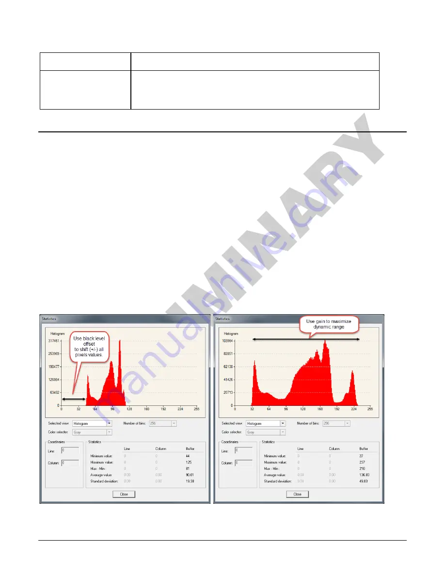
A histogram or line profile (available in CamExpert) can provide useful information to determine 

the optimal settings for the typical image expected for an application. For example, the following 

histograms illustrate the effect of offset and gain applied to the original image to try to maximize 

the dynamic range. 


Содержание Link HS

Страница 1: ...Linea Camera Link HS Camera User s Manual 16k Monochrome CMOS Line Scan sensors cameras frame grabbers processors software vision solutions P N 03 032 20249 00 www teledynedalsa com ...

Страница 2: ...A Teledyne DALSA is headquartered in Waterloo Ontario Canada We have sales offices in the USA Europe and Asia plus a worldwide network of representatives and agents to serve you efficiently Contact information for sales and support inquiries plus links to maps and directions to our offices can be found here Sales Offices http www teledynedalsa com corp contact offices Technical Support http www te...

Страница 3: ...rge and the Sensor 11 CONNECTORS 12 Power Connector 12 Data Cables 13 Establishing Camera Communications 13 Establishing Data Integrity 14 INSTALL CONFIGURE FRAME GRABBER SOFTWARE 14 Using Sapera CamExpert 14 CAMERA OPERATION 16 CAMEXPERT FOR LINEA CLHS CAMERAS 16 CamExpert Panes 16 Creating a Camera Configuration File in the Host 18 Factory Settings 19 Open the CamExpert Panes 19 TYPICAL SETUP AN...

Страница 4: ...RUCTIONS 48 Electrostatic Discharge and the Sensor 48 Protecting Against Dust Oil and Scratches 48 Cleaning the Sensor Window 49 APPENDIX A GENICAM COMMANDS 50 CAMERA INFORMATION CATEGORY 50 Camera Information Feature Descriptions 50 CAMERA CONTROL CATEGORY 52 Camera Control Feature Descriptions 52 I O CONTROL CATEGORY 53 I O Control Feature Descriptions 53 FLAT FIELD CATEGORY 53 Flat Field Featur...

Страница 5: ...rading and inspection transportation safety and general purpose machine vision The Linea lineup of cameras are compact light weight robust and feature rich including flat field correction multiple ROI and AOI multiple user configuration sets and calibration coefficients for various lighting conditions The Linea CLHS camera is one of a new series of affordable and easy to use digital cameras specif...

Страница 6: ...ody Multiple regions of interest for calibration and data reduction 8 bit or 12 bit output Small flat field and lens shading correction 8 programmable coefficient sets GenICam compliant interfacing Applications Automated optical inspection Security systems High performance sorting systems Materials grading and inspection systems Web inspection General purpose machine vision ...

Страница 7: ...able from http www midwestopticalsystems com Teledyne DALSA Software Platform Sapera LT version 7 50 or higher includes CamExpert GUI application Available for free download http www teledynedalsa com imaging products softw are sapera lt Sapera provides everything needed to develop imaging applications Camera Firmware Embedded within camera GenICam support XML camera description file Embedded with...

Страница 8: ...nk HS compatible connectors each capable of supporting data rates up to 2 1 gigabytes per second GB s The connector can also interface with standard CX4 Active Optical Cable fiber modules where very long data transmission is required up to 300 meters RXC TXC TX1 TX2 TX3 TX4 TX5 TX6 TXC RXC RX1 RX2 RX3 RX4 RX5 RX6 Data Lane 6 Data Lane 0 Command Channel Video Channel Link Camera C2 7M1 Frame Grabbe...

Страница 9: ... H x 52 86 mm D Mass 360 g Operating Temp 0 C to 65 C front plate temperature Optical Interface Sensor to Camera Front Distance 12 mm Sensor Alignment aligned to sides of camera Θ y parallelism x y z Θ z 0 08 or 100 µm 300 µm 300 µm 300 µm 0 3 Operating Ranges Performance Notes Dynamic Range 60 dB Random Noise 3 06 DN rms FFC enabled Broadband Responsivity 80 DN nJ cm2 Gain Nominal range 1x to 10x...

Страница 10: ...entific and medical equipment Radio frequency disturbance characteristics Limits and methods of measurement EN 61326 1 2013 Electrical equipment for measurement control and laboratory use EMC requirements Part 1 General requirements EN 55024 2010 Information technology equipment Immunity characteristics Limits and methods of measurement CISPR 11 Industrial scientific and medical equipment Radio fr...

Страница 11: ...onsivity The responsivity graph describes the sensor s response to different wavelengths of light excluding lens and light source characteristics 0 10 20 30 40 50 60 70 80 90 400 500 600 700 800 900 1000 Responsivity DN nJ cm 2 Wavelength nm Linea 16k Responsivity 12 bit 1x Gain ...

Страница 12: ...nea Camera Link HS Series Overview Linea CLHS Series Camera Effective Quantum Efficiency The quantum efficiency graph describes the fraction of photons at each wavelength that contribute charge to the pixel ...

Страница 13: ...at you power down and disconnect power to the camera before you add or replace system components Cleaning the Device To clean the device avoid electrostatic charging by using a dry clean absorbent cotton cloth dampened with a small quantity of pure alcohol Do not use methylated alcohol To clean the surface of the camera housing use a soft dry cloth To remove severe stains use a soft cloth dampened...

Страница 14: ...ng dimensions Power A Hirose 6 pin 12 V to 24 V DC Control Data B Camera Link HS connector Status C Diagnostic LED See description below Power Connector WARNING Grounding Instructions It is extremely important that you apply the appropriate voltages to your camera Incorrect voltages may damage the camera Input voltage requirements 12 VDC to 24 VDC 2 Amp Before connecting power to the camera test a...

Страница 15: ...a has a single multicolor LED to provide a simple visible indication of camera state The table below summarizes the operating states of the camera and the corresponding LED states When more than one condition is active the LED indicates the condition with the highest priority Establishing Camera Communications Power up the camera and observe the LED which indicates the following status conditions ...

Страница 16: ...cations to recognize the camera s capabilities immediately after connection Installing Sapera LT gives you access to the CamExpert GUI a GenICam compliant application Using Sapera CamExpert CamExpert is the camera GUI supported by the Sapera library When used with a Linea CLHS camera CamExpert allows the user to test all camera operating modes In addition CamExpert can be used to save the camera s...

Страница 17: ...ote The availability of features depends on the CamExpert user setting Not all features are available to all users A note on the CamExpert examples shown here The examples shown for illustrative purposes and may not entirely reflect the features and parameters available from the camera model used in your application ...

Страница 18: ...ng or control parameters without the need to run a separate acquisition program Click on any parameter and a short description is displayed below the Category pane The same context sensitive help is available by clicking on the button then click on a camera configuration parameter Click on the button to open the help file for more descriptive information on CamExpert Note The examples shown may no...

Страница 19: ...t displays parameters only if those parameters are supported by the installed device This avoids confusion by eliminating parameter choices when they do not apply to the hardware in use Display pane Provides a live or single frame acquisition display Frame buffer parameters are shown in an information bar above the image window Control Buttons The Display pane includes CamExpert control buttons Th...

Страница 20: ...ich defines its requirement or complexity The states vary from Beginner features required for basic operation of the device to Guru optional features required only for complex operations CamExpert presents camera features based on their visibility attribute CamExpert provides quick Visibility level selection via controls below each Category Parameter list Less More The user can also choose the Vis...

Страница 21: ...ands are provided Factory Settings The camera has been calibrated and configured at the factory to be ready for operation when first powered up The camera ships and powers up for the first time with the following factory settings Maximum horizontal width 16 384 pixels Internal trigger line rate 10 kHz Internal exposure control exposure time 50 µs Offset 0 Gain 1x lowest value Flat field calibratio...

Страница 22: ...CamExpert second instance select LA_HM_16k07A_00_R from the Device drop down menu Figure 3 CamExpert Camera Control Window At this point you are ready to start operating the camera in order to acquire images set camera functions and save settings ...

Страница 23: ... default configuration of Camera Link full 10 kHz line rate and 50 µsec exposure time If this line rate is too slow for your application you will get a compressed image in the scan direction To increase the line rate use the Internal Line Rate parameter in the Camera Control category Adjust the exposure time refer to the Exposure Controls section Set your camera direction refer to the Pixel Readou...

Страница 24: ... to uniquely identify the connected device The parameters used to select load and save user sets are grouped together under the Camera Information Power up Configuration category Verify Temperature and Voltage To determine the voltage and temperature at the camera use the Refresh Voltage and Refresh Temperature features The temperature returned is the internal temperature in degrees Celsius For pr...

Страница 25: ...esults within 1 of the actual voltage The measurement can be used to set the applied voltage to the camera Pixel Format Use the Pixel Format feature found in the Image Format category to select the format of the pixel to use during image acquisition as either Mono 8 or Mono 12 bit depth Image Format Parameter Description Pixel Format Sets the sensor pixel format Possible values are Mono 8 Mono 12 ...

Страница 26: ... Test Pattern Enable camera sensor test pattern Possible values are Off Image is from the camera sensor Ramp Image is filled horizontally with an image that goes from the darkest possible value to the brightest Alternating Alternating values For 12 bit output pixel values alternate between 1381 0x565 and 2746 0xABA For 8 bit output pixel values alternate between 86 0x56 and 172 0xAC Fixed Pattern ...

Страница 27: ...onfigure the camera to the required EXSYNC and exposure timing and adjust the light level for normal operation If used any horizontal or vertical binning should also be applied Set the system gain to a value that best suits the application refer to the section Gain and Black Level Offset for more information on setting these values The lens should be at the required magnification and aperture and ...

Страница 28: ... selection CamExpert has a default timeout of 20 seconds per command which is too short for the FFC calibration to run fully You can change the default timeout by setting a command line argument in the short cut Right click on the short cut in the start menu and select Properties In the Target field add the switch timeout 60 See below This increases the command timeout to 60 seconds Note that you ...

Страница 29: ... Target After calibration all pixels will be scaled to output this level Range depends on pixel format 8 bit 0 to 255 DN 12 bit 0 to 4095 DN Calibration Sample Size Number of lines to average when calibrating Possible values 2048 or 4096 ROI Offset X Together with ROI Width specifies the range of pixels to be calibrated Pixel coefficients outside this range are not changed It is possible to calibr...

Страница 30: ...than 12 bits Typical use is to subtract minimum pixel value expected and then adjust the gain to up the maximum pixel value to approach full scale Features and limitations are described below Black Level offset is expressed as a digital number providing a offset from the factory setting The factory setting optimized the black level offset for maximum dynamic range under controlled ideal dark condi...

Страница 31: ...l addition after an FPN correction 1 8 of available range Positive values may be used to measure dark noise Depending on the the pixel format different offset ranges are available 12 bit mode available range is 512 to 511 8 bit mode available range is 32 to 31 Gain Floating point digital multiplier applied to each pixel Set the gain as an amplification factor applied to the video signal across all...

Страница 32: ... modes are described below Note The Trigger Mode feature can only be adjusted when the Exposure Time Source parameter is set to Timed The Trigger Mode feature is available in the camera s I O Controls category I O Controls Parameter Description Trigger Mode Off Internal trigger trigger disabled The camera free running mode has a programmable internal timer for line rate and a programmable exposure...

Страница 33: ... determine the three imaging modes using a combination of the Exposure Time Source parameters including I O parameters Exposure Time and Internal Line Rate parameters The feature Exposure Time Source selects the controlling method for the exposure The start of exposure can be driven by an internal timer signal an external trigger signal or a software function call For External Trigger signals the ...

Страница 34: ... off and internal exposure control This mode is not synchronized to an external signal Line rate is the dominant factor when adjusting the line rate or exposure time When setting the line rate exposure time will decrease if necessary to accommodate the new line rate When adjusting the exposure time the range is limited by the line rate and has the following features The Trigger Source feature see ...

Страница 35: ...O Control category selects an external signal line as trigger Line rates and exposure limits are as defined for Internal Programmable Exposure The falling edge of the EXSYNC CC1 signal triggers the start of the internal exposure Programmable Exposure1 Programmable Exposure1 Line Time Programmable Exposure1 Sensor Readout2 Sensor Readout2 Sensor Readout2 LVAL delay3 LVAL CC1 2 µs 1 Exposure time 4µ...

Страница 36: ...Trigger Mode On Camera Control Exposure Time Source Trigger Width Binning Binning is the combining of two or more image sensor pixels to form a new combined pixel A binned image using the same exposure settings as a non binned image will show an improved signal to noise ratio reduced scanning times due to lower spatial resolution and save as a smaller image file size compared with a non binned ima...

Страница 37: ...t category represents the number of horizontal pixels that will be combined added together Image Format Parameter Description Vertical Binning This feature represents the number of vertical photo sensitive cells that are combined added together 2 Horizontal Binning This feature represents the number of horizontal photo sensitive cells that are combined added together ...

Страница 38: ...o four specific areas of the pixel line to be specified where image data will be output Since the AOI feature reduces the amount of data output this has the additional benefit of allowing the cameras to operate at higher line rates when using base or medium camera link modes Full Image Width AOI 1 AOI 2 AOI 3 AOI 4 AOI 2 Offset AOI 3 Offset AOI 4 Offset AOI 1 AOI 2 AOI 3 AOI 4 Resulting Output Ima...

Страница 39: ...Linea CLHS Series Camera Camera Operation 37 AOI Width is used to indicate the width of the AOI Minimum region width is 40 pixels and must be a multiple of 8 base medium and full modes or 10 deca mode ...

Страница 40: ...Operation Linea CLHS Series Camera To initiate operation of the AOI once setup The AOI mode must be changed to Active Be sure to set the frame grabber image width to the sum of all AOI widths set up in the camera ...

Страница 41: ...ustomize resave and restore By default the user settings are shipped with the same settings as the factory set The second drop list allows the user to change the camera configuration any time after a power up see feature UserSetSelector To reset the camera to the factory configuration select Factory Setting and click Load To save a current camera configuration select from User Set 1 through User S...

Страница 42: ...ngs Camera Firmware Updates The user can upload new firmware using the File Access Control features via Sapera CamExpert To update the camera firmware several files must be updated Files include the following Type File Device Firmware Microcode hex file XML XML file Miscellaneous FPGA Code bin file CCI hex file After all files have been transferred to the camera the order is not relevant reboot or...

Страница 43: ...mera To do this use the File Access Control features via Sapera CamExpert Select Miscellaneous file type In the File selector drop down box select CameraData Click Download Save the text file and send the file to Teledyne DALSA customer support if required File Access via the CamExpert Tool In the File Access Control Category click on the Setting button to open the File Access Control dialog ...

Страница 44: ...era s memory location for the uploaded data This menu presents only the applicable data locations for the selected file type Click the Browse button to open a standard Windows Explorer window Select the specific file from the system drive or from a network location Click the Upload button to execute the file transfer to the camera Note that firmware changes require a device reset command from the ...

Страница 45: ...Linea CLHS Series Camera 43 Technical Specifications Mechanical Specifications ...

Страница 46: ...nal Notes on Linea CLHS Identification and Mechanical Identification Label Linea CLHS cameras have an identification label applied to the back side with the following information Model Part number Serial number 2D Barcode CE and FCC logo Made in Canada Statement ...

Страница 47: ...Linea CLHS Series Camera Technical Specifications 45 EMC Declarations of Conformity Please note conformity testing for the Linea CLHS cameras will be complete in early 2017 ...

Страница 48: ...view the sections of interest It is often more important to consider exposure than illumination The total amount of energy which is related to the total number of photons reaching the sensor is more important than the rate at which it arrives For example 5 µJ cm2 can be achieved by exposing 5 mW cm2 for 1 ms just the same as exposing an intensity of 5 W cm2 for 1 µs Light Sources Keep these guidel...

Страница 49: ...ns surface to the second focal point The object distance OD is the distance from the first principal point to the object Primary Points in a Lens System Magnification and Resolution The magnification of a lens is the ratio of the image size to the object size h h m Where m is the magnification h is the image height pixel size and h is the object height desired object resolution size By similar tri...

Страница 50: ... components with extreme care Dust can obscure pixels producing dark patches on the sensor response Dust is most visible when the illumination is collimated The dark patches shift position as the angle of illumination changes Dust is normally not visible when the sensor is positioned at the exit port of an integrating sphere where the illumination is diffuse Dust can normally be removed by blowing...

Страница 51: ...ow may need cleaning The following steps describe various cleaning techniques to clean minor dust particles to accidental finger touches Use compressed air to blow off loose particles This step alone is usually sufficient to clean the sensor window Avoid moving or shaking the compressed air container and use short bursts of air while moving the camera in the air stream Agitating the container will...

Страница 52: ...ed by DFNC versus the GenICam Standard Features Naming Convention SFNC not shown Camera Information Category Camera information can be retrieved via a controlling application Parameters such as camera model firmware version etc are read to uniquely identify the connected device These features are typically read only GenICam applications retrieve this information to identify the camera along with i...

Страница 53: ...from or save current feature settings to The Factory set contains default camera feature settings User camera configuration sets contain features settings previously saved by the user RW Beginner Factory Set Factory Select the default camera feature settings saved by the factory User Set 1 to User Set 8 UserSet1 Select the User Defined Configuration space UserSet1 to UserSet8 to save to or load fr...

Страница 54: ...ureLineRate value DFNC Beginner Exposure Time Source ExposureMode Sets the operation mode for the camera s exposure Beginner Timed Timed The exposure duration time is set using the Exposure Time feature and the exposure starts with a LineStart event Trigger Width TriggerWidth Uses the width of the trigger signal pulse to control the exposure duration Use the Trigger Activation feature to set the p...

Страница 55: ...aging application Flat Field Feature Descriptions The following table describes these features along with their view attribute Display Name Feature Values Description Standard View Mode flatfieldCorrectionMode Sets the mode for flat field correction DFNC Beginner Off Off Flat field correction is disabled On On Flat field correction is enabled Initialize Initialize Reset all FPN coefficients to 0 a...

Страница 56: ... following table describes these features along with their view attribute Display Name Feature Values Description Standard View Pixel Coding PixelCoding Output image pixel coding format of the sensor RO Beginner Mono Mono Monochrome format Pixel Color Filter PixelColorFilter Indicates the type of color filter applied to the image RO Beginner None None No filter applied on the sensor Test Pattern T...

Страница 57: ...ctive AOI Count multipleAOICount Specifies the number of AOIs Area of Interest available for the X axis DFNC Expert AOI Selector multipleAOISelector Select an AOI Area of Interest when Multiple AOI Mode is enabled Selector range is from 1 to the MultipleAOICount value DFNC Expert AOI Offset X multipleAOIOffsetX Horizontal offset in pixels from the origin to the selected AOI Area of Interest The of...

Страница 58: ... transmitters enable after sending Acquisition start 1 00 Guru DFNC Next CLHS Device Configuration One cable seven lanes One cable four lanes One cable one lanes Two cable seven lanes Two cable four lanes Two cable one lanes clhsNext DeviceConfig When the camera is next powered up the specified CLHS lane configuration will be set for the camera 1 00 Guru DFNC CLHS 8b 10b Receive Error Count select...

Страница 59: ...nsistency before activating them Invisible Register Check DeviceRegistersCheck Performs an explicit register set validation for consistency Invisible Registers Valid DeviceRegistersValid States if the current register set is valid and consistent Invisible File Access Control Category The File Access control in CamExpert allows the user to quickly upload various data files to the connected camera T...

Страница 60: ...sed to open a file on the device Guru Read Read Select READ only open mode Write Write Select WRITE only open mode File Access Buffer FileAccessBuffer Defines the intermediate access buffer that allows the exchange of data between the device file storage and the application Guru File Access Offset FileAccessOffset Controls the mapping offset between the device file storage and the file access buff...

Страница 61: ... 0000 FLASH_ERROR 100 0000 NO_FPGA_Code 1000 0000 NO_COMMON_SETTINGS 1 0000 0000 NO_FACTORY_SETTINGS 10 0000 0000 NO_USER_SETTINGS 100 0000 0000 NO_FLAT_FIELD Corrections 1000 0000 0000 NO MISC corrections 1 0000 0000 0000 NO_FPN Correction 10 0000 0000 0000 NO_FPN Correction 100 0000 0000 0000 NO_PRNU Correction 1000 0000 0000 0000 NO_FEED Through Correction 1 0000 0000 0000 0000 NO_LINEARITY Cor...

Страница 62: ...pendix C Error and Warning Messages Linea CLHS Series Camera Operational Error Codes Code Description 0X8002 Invalid Parameter 0xC01C CPA_TOO_MANY_OUTLIERS 0x401E USER_FPN_CLIPPING 0x401F FLAT_FIELD_CLIPPING ...

Страница 63: ...Linea CLHS Series Camera 61 Document Revision History Revision Description Date 00 Preliminary release December 12 2016 ...

Отзывы: