background image

User Manual 


English 


Installation 

Make sure all devices are switched off before making any connections!  

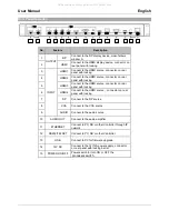
Connect the source devices to the processor switch input ports. 4 HDMI ports, 1 DisplayPort and 1 VGA 

port is provided. Then connect the high definition displays to the processor switch output ports. When all 

the connections are made, connect the power supply and switch on. 

Once all the connections have been made, switch on the devices in this order: displays, processor 

switch, source devices. Please wait for the devices to handshake and for the signals to appear.  

Rack Mount Installation 

Take the following steps to attach the two brackets to the unit and install into a rack. 


Remove all cables and power supply before mounting the Processor switch in the rack 


Place the unit on a sturdy surface 


Attach a bracket to the left side of the unit by using a screw driver and four screws 


Attach the other bracket to the right side of the unit by using a screw driver and four screws 


Make sure that your path to the rack is unobstructed. 


Slide the unit into the rack and position using the attached L brackets so that the slots in the brackets 

are positioned over the appropriate mounting holes in the side rails of the rack 


Securely fasten the unit into the rack by using four rack screws (not supplied), installing two of the 

screws on each side of the unit. Use a screw driver to tighten the screws on each side of the unit. 


All manuals and user guides at all-guides.com

Содержание 38156

Страница 1: ...y 2018 6 Port Multi AV to HDMI 2 0 18G Processor Switch with PiP User Manual English No 38156 lindy com Tested to Comply with FCC Standards For Home and Office Use All manuals and user guides at all g...

Страница 2: ...rews Lindy QIG Features Allows up to 4 Inputs to be shown one a single screen PIP POP Multi View and Full screen modes available Pre set Layout options at the touch of a button Complete control over w...

Страница 3: ...rackets to the unit and install into a rack Remove all cables and power supply before mounting the Processor switch in the rack Place the unit on a sturdy surface Attach a bracket to the left side of...

Страница 4: ...n 6 DP Press to select the DP input in full screen Press to select DP audio in multi view screen 7 VGA Press to select the VGA input in full screen Press to select VGA audio in multi view screen 8 LAY...

Страница 5: ...on rear panel with locking 7 DP Connect to the DP source 8 VGA Connect to the VGA source 9 AUDIO Connect to the audio source 10 AUDIO OUT Connect to the audio amplifier 11 ETHERNET Connect to PC NB or...

Страница 6: ...HDMI 1 audio in multiview mode H 2 Select HDMI 2 in full screen mode Select HDMI 2 audio in multiview mode H 3 Select HDMI 3 in full screen mode Select HDMI 3 audio in multiview mode H 4 Select HDMI 4...

Страница 7: ...full screen mode 9 Flip Flip display screen in full screen mode 10 Custom Layout 1 Select the custom screen layout 1 2 Select the custom screen layout 2 3 Select the custom screen layout 3 4 Select th...

Страница 8: ...ected will be displayed with one large window along the top with three smaller underneath Layout D The Inputs selected will be displayed with three small along the top and 1 large window underneath La...

Страница 9: ...5 255 255 0 You can now use your browser to access the web GUI by using the IP address of the unit This can be changed under the system settings on the GUI you can choose from your own manual IP addre...

Страница 10: ...I2 4 HDMI3 5 DP 6 VGA 7 Mute Press Confirm after setting to finish or press Cancel to ignore the modification 3 Full Screen Setting Flip Flip video display in full screen mode 1 On 2 Off default Press...

Страница 11: ...ore the modification 7 Window Info Main Screen Window A Sub Screen Window B Window C Window D Window A input source HDMI1 default Window B input source HDMI2 default Window C input source HDMI3 defaul...

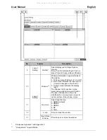
Страница 12: ...1 Window name Window A B C and D 2 Blue mark Indicates the Input source it can be changed in Gear icon 3 Orange mark Indicates the display layer The Window A to D position can be moved when clicking m...

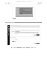
Страница 13: ...User Manual English Factory Reset Web GUI Press the Load Default icon to reset to the default settings for the Web UI All manuals and user guides at all guides com...

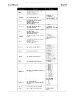
Страница 14: ...Default 50 RBRI SHOW BRIGHTNESS CURRENT VALUE FOR OUTPUT SCON N SET CONTRAST VALUE FOR OUTPUT N 0 100 Default 50 RCON SHOW CONTRAST CURRENT VALUE SSAT N SET SATURTATION VALUE FOR OUTPUT N 0 100 Defau...

Страница 15: ...RENT VALUE WINDOW A D WINDOW 1 4 VERTICAL SIZE 0 59 SWIN N M SET OUTPUT WINDOW ON OFF WINDOW N 1 4 1 A 2 B 3 C 4 D M 0 OFF 1 ON RWIN N SHOW OUTPUT WINDOW WINDOW N 0 4 1 A 2 B 3 C 4 D 0 ALL SPRI N M SE...

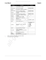
Страница 16: ...Y SET STATIC GATEWAY ADDRESS N 0 255 M 0 255 X 0 255 Y 0 255 RGAADD SHOW STATIC CURRENT GATEWAY ADDRESS IPCONFIG SHOW ETHERNET ADDRESS DEFAULT RESET THE UNIT TO FACTORY DEFAULTS SMUTE 0 1 SET MUTE AUD...

Страница 17: ...UT SWAP NA Rotate NA Flip NA HDMI4 NA Rotate NA Flip NA HDMI4 NA Rotate NA Flip NA HDMI4 NA Rotate NA Flip NA HDMI4 NA Rotate NA Flip NA HDMI4 NA Rotate NA Flip NA HDMI4 NA 480p INPUT SWAP NA Rotate N...

Отзывы: