background image


                              9 

4. 

Trouble Shooting


The Switch can be easily monitored through panel indicators to 
assist in identifying problems. This section describes common 
problems you may encounter and where you can find possible 
solutions. 
 

??

Diagnosing LED Indicators 


IF Link indicator does not light up after making a connection. 
You may check whether network interface (e.g., a network 
adapter card on the attached device), network cable, or switch 
port is defective or not. Be sure the cable is plugged into both 
the Switch and corresponding device. Verified the proper 
cable type is used and its length does not exceed specified 
limits. 
 

??

Power 


IF the power indicator does not turn on when the power cord is 
plugged in, you may have a problem with power outlet, or 
power cord. However, if the switch powers off after running for 
a while, check for loose power connection, power loses or 
surges at power outlet. If you still cannot resolve the problem, 
contact your local dealer for assistance. 
 

??

Cabling 


RJ-45 Ports: 

Use unshielded twisted-pair (UTP) or shield 

twisted-pair (STP) cable for RJ-45 connections: 100O 
Category 3,4 or 5 Cable for 10Mbps connections or 100O 
Category 5 Cable for 100Mbps connections. Also be sure that 
the length of any twisted-pair connection does not exceed 100 
meters ( 328 feet ). 

Содержание 25051

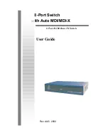
Страница 1: ...8 Port Switch with Auto MDI MDI X 8 Port 10 100 Base TX Switch User Guide Rev AUG 2002...

Страница 2: ...detect the speed of the device that you plug into it to allow you to use both 10 and 100Mbps device They feature a store and forward switching and it can auto learn and store source address on an 1K e...

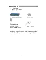
Страница 3: ...s Guide 8TP Auto MDI MDI X Switch Rubber Feet DC power Adapter User s Guide Figure 1 2 Package Contents Compare the contents of your 8 Port Switch with the standard checklist above If any item is miss...

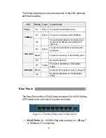
Страница 4: ...witch are the same 164mm W X 100mm D x 26mm H Front Panel The LED indicators are located on the frond panel of the Switch They provide a real time indication of systematic operation status The Front P...

Страница 5: ...ection LED Status Color Description Power On Green The power of the Switch is On On Green The port is connecting with 100Mbps 100Mbps Off The connection between the Switch and the device is 10Mbps if...

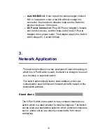
Страница 6: ...Network Application This section provides you a few examples of network topology in which the 8 Port Switch is used the Switch is design to be used as a desktop or segment switch The switch automatic...

Страница 7: ...hed workgroup to form a large switched network You can connect anyone switch port to hub or switch without crossover cable by the Auto MDI MDI X function In the below illustration two Switches are use...

Страница 8: ...8 Figure 3 2 Example of enlarging your network...

Страница 9: ...he proper cable type is used and its length does not exceed specified limits Power IF the power indicator does not turn on when the power cord is plugged in you may have a problem with power outlet or...

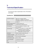
Страница 10: ...s Ethernet port 148 800 pps per Fast Ethernet port LED Indicators Per Port Link Activity Full Collision 100M Per Unit Power Network Cables 10Base T 2 pair UTP Cat 3 4 5 cable 100m EIA TIA 568 100 ohm...

Страница 11: ...be determined by turning the equipment off and on the user is encouraged to try to correct the interference by one or more of the following measure Reorient or relocate the receiving antenna Increase...

Отзывы: