5
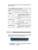
The following table provides descriptions of the LED statuses
and their meaning.
Rear Panel
The Rear Panel of the 8 -Port Switch consists of 8x 10/100 N-Way
UTP switch ports, and one DC power connector.
Figure 2-4. The Rear Panel of the 8-Port Switch
??
RJ-45 Ports:
8x 10/100N-Way auto-sensing for 10Base-T
or 100Base-TX connection.
LED
Status Color
Description
Power
On
Green
The power of the Switch is On
On
Green
The port is connecting with 100Mbps.
100Mbps
Off
The connection between the Switch and
the device is 10Mbps, if the LINK/ ACT
light is on.
On
Green
The port is successfully connecting with
the device.
Blinks
The port is receiving or transmitting data.
LNK /ACT
Off
No device attached.
On
Yellow
The port is operating in Full-duplex
mode.
Blinks
Collision of Packets occur s in the port.
FDX/COL
Off
No device attached or in half-duplex
mode.

