background image


 29 


10. Cleaning 

10.1 Basics 

Cleaning should be carried out in accordance with the operator's 
own company rules, and cleaning agents and devices and the 
personal protective equipment to be used should likewise be 
selected in accordance with those rules. Only cleaning agents 
compatible with the materials may be used for cleaning. 
Completely remove any cleaning agent residue left on the 
product and rinse with clear water. Unauthorized persons must 
be kept away. Use signage to indicate wet areas. 
 

10.2 Interior cleaning 

The interior normally does not need to be cleaned. The interior 
of the product must be cleaned if incorrect or contaminated 
lubricant accidentally enters the product. Please contact our 
Service department. 
 

10.3 Exterior cleaning 

Do not allow any cleaning fluid to enter the interior of the 
product during cleaning. 

<  


 WARNING 


Risk of fatal electric shock 


Cleaning work may only be performed on 
products that have been de-energized first. When 
cleaning electrical components, be mindful of the 
IP enclosure rating.  


<  


 WARNIG 


Serious injury from contact with or inhalation 
of hazardous substances 


Wear personal protective equipment. Observe the 
safety data sheet (SDS) of the hazardous 
substance. Avoid contaminating other objects or 
the environment during cleaning. 


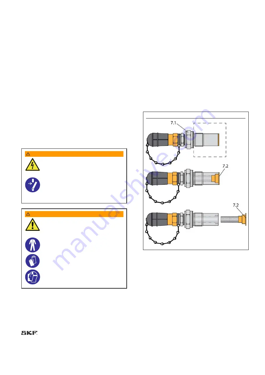
10.4 Cleaning the filter of the filling 
connection 

If the filter of filling connection 169-460-406 requires cleaning 
due to contamination, proceed as follows: 

1.

 Loosen the filling connection at its hexagon (

7.1

) with a fork 

wrench AF 27.  

2.

 Loosen the filter (

7.2

) at its hexagon socket (AF 6) and 

remove it. 

3.

 Clean filter (

7.2

) with appropriate detergent and dry, e.g. with 

compressed air. 

4.

 Mount all parts again in reverse order. 


Tightening torques: 
7.2 Filter (AF 6): 10 Nm ± 1.0 Nm 
7.1 Filling connection (AF 27) 20 Nm ± 2.0 Nm 


Fig. 21


Cleaning the filter of the filling connection 


Содержание SKF CLP

Страница 1: ...ation pump CLP for progressive systems DC Versions without Control Unit Date 29 04 2021 Document no 951 171 064 EN Version 04 Read this manual before installing or commissioning the product and keep it at hand for later reference ...

Страница 2: ...nal UK Declaration of incorporation according to the Supply of Machinery Safety Regulations 2008 No 1597 Annex II SKF Lubrication Systems Germany GmbH Heinrich Hertz Str 2 8 DE 69190 Walldorf hereby declares under sole responsibility that the partly completed machinery complies with the essential health and safety requirements of UK legislation Supply of Machinery Safety Regulations 2008 No 1597An...

Страница 3: ...f break up during operation YES YES As to 1 3 2 Not fully complied with The operator has to secure the lubrication system against excessive pressure For this purpose a pressure relief valve with max 270 bar opening pressure must be provided on each pump element 1 3 4 Risks due to surfaces edges or angles YES YES 1 3 7 Risks related to moving parts YES YES 1 3 9 Risks of uncontrolled movements YES ...

Страница 4: ...ny Tel 49 0 6227 33 0 Fax 49 0 6227 33 259 Authorized local distributors Great Britain SKF U K Limited 2 Canada Close Banbury Oxfordshire OX16 2RT GBR North America SKF Lubrication Business Unit Lincoln Industrial 5148 North Hanley Road St Louis MO 63134 USA South America SKF Argentina Pte Roca 4145 CP 2001 Rosario Santa Fe EEU Area LLC SKF 121552 Russia Moscow Yartsevskaya Street 19 Block A Floor...

Страница 5: ...ent R 22 6 4 Mount pressure control valve 22 6 5 Connection of the lubrication line 22 6 6 Electrical connection 23 7 First start up 24 7 1 Inspections prior to initial start up 24 7 2 Inspections during initial start up 24 7 3 Triggering an additional lubrication cycle 25 7 3 1 25 7 3 2 Pumps without controller 25 7 4 Acknowledge receipt of a fault indication 25 8 Operation 26 8 1 Priming a pump ...

Страница 6: ...rty or malfunctions Illustrations The illustrations used depict a specific product For other products they may have the function of a diagram only This does not alter the basic workings and operation of the product Text layout First order bulleted lists Items on a bulleted list start with a solid black dot and an indent Second order bulleted lists If there is a further listing of subitems the seco...

Страница 7: ...ffered by SKF for the respective product Any unclear points regarding proper condition or correct assembly operation must be clarified Operation is prohibited until issues have been clarified The painting of all plastic parts visual monitoring devices and seals is prohibited Tape or remove parts completely before painting Maintain electrical equipment in proper condition This must be ensured by re...

Страница 8: ...s in areas with high exposure to ozone UV light or ionizing radiation Use to supply convey or store hazardous substances and mixtures as defined in the CLP Regulation EC 1272 2008 or GHS with acute oral dermal or inhalation toxicity or substances and mixtures that are marked with hazard pictograms GHS01 GHS06 and GHS08 Use to supply convey or store Group 1 fluids classified as hazards as defined i...

Страница 9: ... approval mark E1 confirms that an ECE design certification motor vehicle components subject to approval was issued for the product indicated on the type identification plate 1 14 Notes related to the UKCA marking The UKCA conformity marking confirms the product s conformity with the applicable legal provisions of Great Britain 1 15 Notes on EAC mark The EAC mark of conformity confirms that the pr...

Страница 10: ...and lubrication lines for the stated pressures Do not mount lubrication lines to moving parts or friction points If this cannot be avoided use spring coils respectively protective conduits Fire hazard or damage to the pump due to an operation with defective electrical components e g Connection cables and plugs B C D E F G H Check the electrical components with regard to damages before the first us...

Страница 11: ...ck after just one week 2 5 Avoidance of faults and hazards To avoid faults and hazards please observe the following When handling lubricants observe the relevant safety data sheet SDS and any hazard labeling on the packaging Due to the large number of additives some lubricants that meet the pumpability requirements specified in the manual are not suitable for use in centralized lubrication systems...

Страница 12: ...icable a push button for triggering an additional lubrication Pump housing upper part flat Pump housing upper part flat 12a is used as a standard for pumps without M12 plug 3 2 Electrical connections The electrical connections 10 1 to 10 4 are used for power supply or as signal or communication connections Depending on the specific pump design the following electrical connections are possible Fig ...

Страница 13: ...he MIN marking must not be undergone when operating the pump Depending on the concrete pump version there are different types of reservoirs with and without low level signal The follower plate of pumps with low level signal has an integrated solenoid that sends a low level signal when the reed contact in the contact rod 11 is reached NOTICE Damage to the superior machine in case of pump failure du...

Страница 14: ...C 60529 4x Nema 4x Nema Max switching capacity 5 W 5 VA 5 W 5 VA Switching voltage of low level signalLeermeldung 10 30 V AC DC 10 30 V AC DC Max switching current 500 mA 500 mA Protection class Connection Nominal voltage IEC 61140 Protection class Connection Signal line IEC 61140 1 The minimum admissible ambient temperature assumes that the lubricant used can be pumped 2 Pumps with follower plate...

Страница 15: ...15 4 1 Diagram relative duty cycle Table 5 A Pump runtime in minutes B Minimum pause time in minutes ...

Страница 16: ... 15 ft lb D Pump element to housing 20 Nm 2 0 Nm 14 43 ft lb 0 15 ft lb E Pressure control valve in pump element 6 Nm 0 5 Nm 4 43 ft lb 0 07 ft lb F Central screw of the square plug no figure 0 5 Nm 0 37 ft lb H Optional filling connection to housing 20 Nm 2 0 Nm 14 43 ft lb 0 15 ft lb Additionally for pumps with filling connection 169 460 406 observe the tightening torques stated in chapter Clean...

Страница 17: ...ion diagrams Fig 9 Pump with follower plate Pump with follower plate and low level signal Table 6 Hydraulic connection diagram following ISO 1219 1 2019 01 1 Reservoir 5 Low level signal 2 Pump P Pressure line 3 Filler fitting ...

Страница 18: ...n for additional lubrication left side Voltage supply 1 12 VDC 2 24 VDC Corrosion protection class 3 C3 not selectable Follower plate F With not selectable Filling from top X Without not selectable PUMP CLP G X X 3 F X X Outlet left side see Table 7 Outlet center see Table 7 Outlet right side see Table 7 Application X Industry M Mobile Electrical connection upper right side see Table 8 Electrical ...

Страница 19: ...Electrical connections Upper right side respectively upper left side Lower left side respectively lower right side Code Connection Code Connection X no connection X no connection A M12 plug 4 pole A coded 4 Bayonet plug 4 pole 7 Bayonet plug 7 pole W Square plug 3 PE Table 9 Lubricants Code Lubricant Code Lubricant XX without lubricant AB Aralub HLP 2 FA Fuchs Renocal FN 745 94 L3 Linde Heavy duty...

Страница 20: ...riate measures e g heating to prevent the condensation of water Before usage check products for damage that may have occurred during storage This applies in particular to parts made of plastic due to embrittlement 5 4 Storage temperature range For parts not filled with lubricant the permitted storage temperature is the same as the permitted ambient temperature range see Technical data 5 5 Storage ...

Страница 21: ...t space for maintenance work or for attachment of further components to build a centralized lubrication system to the pump by leaving a free space of at least 100 mm into each direction in addition to the stated dimensions Fig 11 Installation dimensions 6 2 Installation bores NOTICE Risk of damage to the superior machine and to the pump Drill the mounting bores on non load bearing parts of the sup...

Страница 22: ...6 Nm 0 5 Nm 3 Repeat procedure for each assembled pump element Fig 15 Mount pressure control valve 6 5 Connection of the lubrication line CAUTION Risk of falling Exercise care when dealing with lubricants Bind and remove spilled or leaked lubricants immediately NOTICE Damage to the superior machine due to incorrect planning of the centralized lubrication system All components for setting up the ce...

Страница 23: ...cure against being switched on again Verify that no power is being applied Earth and short circuit the product Where needed cover neighbouring units that are live Observe the following installation instructions for safe connection Electrical connection must be carried out according to the prescriptions of the standard series DIN VDE 0100 respectively IEC 60364 Connect the electric lines in such wa...

Страница 24: ...tated in the Technical data All components such as lubrication lines and metering devices have been correctly installed Product protected with adequate pressure control valve No visible damage contamination and corrosion Any dismantled protection and monitoring equipment has been reassembled and checked for correct function All safety relevant markings on the product are available and in proper co...

Страница 25: ...on NOTE An additional lubrication can be triggered during the pump s pause time only 7 3 2 Pumps without controller 7 3 2 1 Additional lubrication in case of pumps without controller Please see the documentation of the superior machine or machine controller if you want to trigger an additional lubrication for pumps without controller 7 4 Acknowledge receipt of a fault indication Please see the doc...

Страница 26: ...ect filler pump with filling connection 7 1 or filler fitting 4 4 Switch on filler pump and fill the space below the follower plate with lubricant carefully and completely see Fig 17 5 Switch off filler pump as soon as all air has escaped from below the follower plate 6 Remove sticker G and slowly and carefully pull vent cord C downward out of the pump 7 Switch on filler pump and fill reservoir wi...

Страница 27: ...ller pump with filler fitting 4 2 Switch on filler pump and fill reservoir until shortly below the MAX marking 3 Switch filler pump off and remove it from filler fitting 4 of pump 4 Place protective cap onto filler fitting of pump again Fig 20 Regular filling via filler fitting ...

Страница 28: ...the previously indicated connections correspond to the specifications stated in the Technical data All components such as lubrication lines and metering devices have been correctly installed Product protected with adequate pressure control valve No visible damage contamination and corrosion Any dismantled protection and monitoring equipment has been reassembled and checked for correct function Any...

Страница 29: ...during cleaning WARNING Risk of fatal electric shock Cleaning work may only be performed on products that have been de energized first When cleaning electrical components be mindful of the IP enclosure rating WARNIG Serious injury from contact with or inhalation of hazardous substances Wear personal protective equipment Observe the safety data sheet SDS of the hazardous substance Avoid contaminati...

Страница 30: ...e the vent pipe 14 on the bottom side of the pump housing by means of an Allen wrench AF 6 14a 2 Remove the contamination inside the vent pipe with an adequate tool and with compressed air where necessary 3 Screw the vent pipe 14 back into the pump housing by means of the Allan wrench 14a Tightening torque 3 Nm 1 0 Nm Fig 22 Cleaning the vent pipe ...

Страница 31: ...o initiate further measures If the fault cannot be determined and remedied please contact our Customer Service Pump runs but does not supply lubricant or supplies an insufficient amount of lubricant Blockade fault within the centralized lubrication system Defective check valve Defective pressure relief valve Suction bore of a pump element is clogged Pump element R wrongly adjusted Air pockets in t...

Страница 32: ...the pressure control valve 5 3 Remove the old seal of the pump element on the pump housing if necessary 2 Screw a new pump element 5 into the pump housing together with a new gasket Tightening torque 20 Nm 2 0 Nm 3 Then screw a new pressure control valve 5 3 into the pump element 5 Tightening torque 6 Nm 0 5 Nm Fig 23 Check pump element and replace pressure control valve 13 Shutdown disposal 13 1 ...

Страница 33: ...data Table 13 14 2 Pressure control valves 270 bar plug in type for tube Ø 6 Designation Qty Part number Fig SVTSV 270 R1 4 1 8 NPTFI NIP00R A 1 270864 SVTSV 270 R1 4 6 1 624 29036 1 SVTSV 270 R1 4 6 NIPOOL 1 624 77803 1 SVTSV 270 R1 4 6 NIPOOR 1 624 77802 1 Legend NIPOOL Lubrication fitting left side NIPOOR lubrication fitting right side NPTFI self sealing tapered pipe thread female Table 14 14 3...

Страница 34: ...mber Fig Cap screw M22x 1 5 including gasket to close unneeded outlets 1 519 60445 1 Table 17 14 6 Filling connection plug in type Designation Qty Part number Fig Optional filling connection with fitting for quick coupling for filling with lubrication grease with a filter 320 μm from the bottom via the lower part of the housing 1 169 460 406 Table 18 14 7 Filling connection plug in type Designatio...

Страница 35: ...nnection sleeve M28x2 1 5590 00000002 Table 20 14 9 Filling connection screwable Designation Qty Part number Fig Optional filling connection for filling with lubrication grease from the bottom via the lower housing part connection sleeve M26x1 5 1 538 36763 1 Table 21 14 10 Vent pipe assy Designation Qty Part number Fig Vent pipe assy to vent the reservoirs of CLP pumps 1 5590 00000014 ...

Страница 36: ...ble Designation Qty Part number Fig Connection cable 10 m with bayonet socket 4 4 poles 1 664 34167 9 Connection cable 10 m with bayonet socket 7 7 poles 1 664 34428 3 Connection cable 10 m with square plug connection socket black 1 664 36078 7 Adapter cable 0 5 m with 7 pole bayonet socket for connection of a CLP Basic pump to the signal line of a KFA pump to be replaced 1 6640 00000068 ...

Страница 37: ...ion NO Normally open contact n c Not connected HLW Prewarning high level signal SLZ Fault good signal 30 Positive pole voltage battery HLA High level signal overfull CS Cycle switch 31 Negative pole ground battery MC 15 Machine contact ignition CS Cycle switch 54 Brake light voltage trailers Err Fault good signal X1 1 Plug on the pump DK Pushbutton additional lubrication BG Piston detector X1 2 So...

Страница 38: ...in these instructions See type identification plate of the pump for specific pump type identification code features Table 26 Connection diagram valid for pumps with the following equipment features 7 pole bayonet plug Pushbutton additional lubrication Low level indication 12 or 24 VDC Mobile Fig 24 1 Contact closes when filling level is at minimum ...

Страница 39: ...27 Connection diagram valid for pumps with the following equipment features 7 pole bayonet plug Pushbutton additional lubrication Low level indication 4 pole M12 plug A coded 12 or 24 VDC Mobile Fig 25 1 Contact closes when filling level is at minimum ...

Страница 40: ... X_FX ___X MXX 7 7 _ Table 28 Connection diagram valid for pumps with the following equipment features 7 pole bayonet plug Low level indication 12 or 24 VDC Mobile Fig 26 1 Contact closes when filling level is at minimum ...

Страница 41: ...4 4 _ Table 29 Connection diagram valid for pumps with the following equipment features 1 x 4 pole M12 plug A coded Low level indication 12 or 24 VDC 1 x 4 pole bayonet plug Mobile Fig 27 1 Contact closes when filling level is at minimum ...

Страница 42: ...15 6 CL_ __XXY Z_ X___ ___X MXX 7 7 _ Table 30 Connection diagram valid for pumps with the following equipment features 1 x 7 pole bayonet plug Pushbutton additional lubrication 12 or 24 VDC Mobile Fig 28 ...

Страница 43: ...43 15 7 CL_ __XXX_ X__X ___X MXX 4 4 _ Table 31 Connection diagram valid for pumps with the following equipment features 1 x 4 pole bayonet plug 12 or 24 VDC Mobile Fig 29 ...

Страница 44: ...Connection diagram valid for pumps with the following equipment features 1 x 4 pole M12 plug A coded Pushbutton additional lubrication 24 VDC 1 x 4 pole bayonet plug Low level indication Industrial Fig 30 1 Contact closes when filling level is at minimum ...

Страница 45: ... W W _ Table 33 Connection diagram valid for pumps with the following equipment features 1 x 4 pole M12 plug A coded Low level indication 24 VDC 1 x 4 pole bayonet plug Industrial Fig 31 1 Contact closes when filling level is at minimum ...

Страница 46: ...6 15 10 CL_ __XXY Z_ X___ ___X XXX W W _ Table 34 Connection diagram valid for pumps with the following equipment features 1 x square plug 3 PE Pushbutton additional lubrication 24 VDC Industrial Fig 32 ...

Страница 47: ...47 15 11 CL_ __XXX_ X___ ___X XXX W W _ Table 35 Connection diagram valid for pumps with the following equipment features 1 x square plug 3 PE 24 VDC Industrial Fig 33 ...

Страница 48: ...48 15 12 China RoHS table Table 36 ...

Страница 49: ...tered trademark of the SKF Group eLube is a trademark of the SKF Group SKF Group 2021 Reprint or reproduction of the contents of this information even in part is permitted only with SKF s prior written consent 951 171 064 EN 29 04 2021 ...

Отзывы: