


Subject
to
modifications
Page Number 7 of 28
2.1B-38008-A01
QLS 311
Form 403074
Installation and Operation Instructions
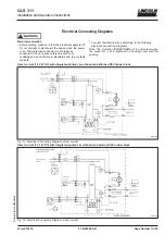
Electrical Connecting Diagrams
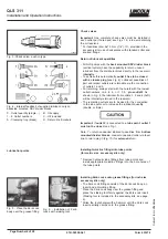
Electrical connection
Before starting, make sure that the electrical supply is off.
Do not connect or disconnect the device when the power
is on. The protective conductor must always be
connected. Check to ensure this line section is
undamaged and conforms to standards and the contacts
are safe.
* Connect the electric wires according to the following
electrical connecting diagrams.
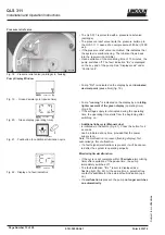
Note: The protection IP6K9K (NEMA 4) is guaranteed when
the socket (x1, x2) is tightened on housing cover with flat
packing.
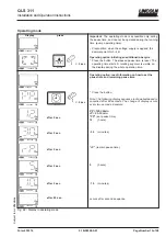
Direct current (12, 24 VDC) with integrated printed circuit board and attached SSV divider block
4253a00
Direct current (12, 24 VDC) with integrated printed circuit board and external SSV divider block
Fig. 11- Electrical Connecting Diagram, direct current
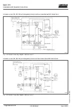
4258a00
Fig. 12- Electrical Connecting Diagram, direct current