


Subject to modifications
Page 7 of 16
User Manual
Operation Instructions
4.1EN-10004-A08
LINCOLN G
MB
H • P
OSTFACH
1263 • D-69183 W
ALLDORF
• T
EL
+49 (6227) 33-0 • F
AX
+49 (6227) 33-259
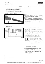
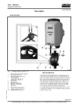
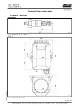
Installation, continuation
Connection of the Lubricant Supply
Connect the port on the bottom of reservoir 5 (Fig. 1) with
supply line B (Ø 12 mm) and with MOP inlet port 4.
Use of Quicklinc Connecting Elements
6051b03
Fig. 2
Connection of Quicklinc connecting element and line
Connect
Push the line in the direction of arrow A (Fig. 2) into the
Quicklinc connecting element until it stops.
Disconnect
Press the line together with pliers B in the direction of
arrow A into the Quicklinc connecting element in order to
loosen the fastening clamps.
Hold pliers B tight and pull out the line in the opposite
direction to arrow A.
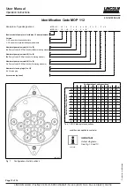
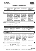
Pump Elements
6757b07
Fig. 3
Pump Element
Pump elements are available in 3 versions:
without/ with 1/ with 2 metering washers.
The MOP can be supplied with up to 12 preassembled
pump elements.
The output of a pump element depends on the number of
preassembled metering washers and the speed of the
driving shaft provided by the user.
Preassembled pump elements can be unscrewed for
replacement purposes.
Instead of a pump element, the MOP can also be
equipped with a closure plug at the intended port.
6001a02
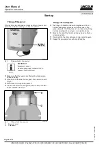
IMPORTANT
To avoid the emptying of the full MOP,
interrupt the lubricant supply from the res-
ervoir and reduce the oil level in the MOP.
Make sure to check the lube points visually
in order to avoid unintended lubricant
penetration.
Connection of Lube Points
Connect respectively one lube point (brush, felt strip,
Fig.
6
) with a pump element of suitable output. Therefore
use feed line Ø 6 mm (Pos. C).
In any application, make sure that the oil quantity is dis-
tributed evenly over the whole width of the link chain
(Fig. 6 & 7 in Fig. 6).


