


Page 6 of 16
User Manual
Operation Instructions
Subject to modifications
4.1EN-10004-A08
LINCOLN GmbH • Postfach 1263 • D-69183 Walldorf • Tel +49 (6227) 33-0 • Fax +49 (6227) 33-259
Safety Instructions, continuation
Installation
1013A94
ATTENTION!
The use of any spare parts can result in
serious damage to your lubrication device.
Therefore, for the operation of your lubri-
cation device use only original spare
parts
1)
by Lincoln GmbH.
1)
See as of page 14 “Spare Parts and Accessories“
6001a02
IMPORTANT
Observe the installation guidelines and
instructions of the machine/ unit manufac-
turer when drilling and welding, as well as
the specified minimum distance on vehicle/
chassis frames for holes between up-
per/lower rim of the frame or between two
bores.
Installation and Maintenance of Lubricating Hoses
1013A94
ATTENTION!
The operational safety of the MOP (me-
chanically-driven oil pump) is only guaran-
teed with a professional installation and
maintenance of hydraulic hoses/lines.
Observe the following points!
Lubrication lines
may never be subjected to torsion
must be installed twist-free
must not rub against metal components or edges
are to undergo regular visual checks and must be ex-
changed in the case of wear.
Pay attention with non linear installations to allow for as large
a bending radius as possible. Avoid kinks! In constricted
installation conditions use pipe elbow unions to avoid the
danger of kinking behind the hose socket.
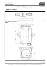
Installation
Location & Fixation
B-MOP112-010a08
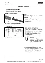
Fig. 1
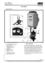
Installation of MOP and reservoir
Install the MOP 1 (Fig. 1) vertically and on smooth planes
(//D = max. 0.3 mm) directing the MOP driving shaft 3 to
the prolonged driving shaft A (provided by the user).
MOP driving shaft Ø .……………………………… 8 mm
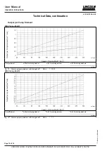
MOP range of speeds:
- Shaft 1 / 2 ……………………………… 30 up to 280 min
-1
Fix the reservoir 5 of the MOP vertically. Make sure to
provide a proper line run B between MOP (on driving
shaft A) and reservoir 5.
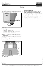
Provide sufficient space for a later filling of the reservoir
from the top (min. 500 mm).
A fastening set consisting of 2 screws, 4 washers and
2 nuts (M8) is included in each MOP 112 supplied (tight-
ening torque 10 Nm ±5%).
1013A94
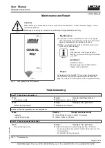
CAUTION!
Before starting any maintenance or repair
work, disconnect the MOP from the power
supply to avoid unintended operation.
1 -
MOP (mechanically-driven oil pump)
2 -
Pump element (1 of optional 12)
3 -
MOP driving shaft
4 -
MOP inlet port
5 -
Reservoir, 5 liters
A -
Driving shaft (to be provided by user)
B -
Lubricant supply line (Ø 12 mm)
C -
Lubricant feed line (Ø 6 mm)
//D - Admissible tolerance of smoothness (0.3 mm)


