background image

A-4

INSTALLATION

SAE-400

®

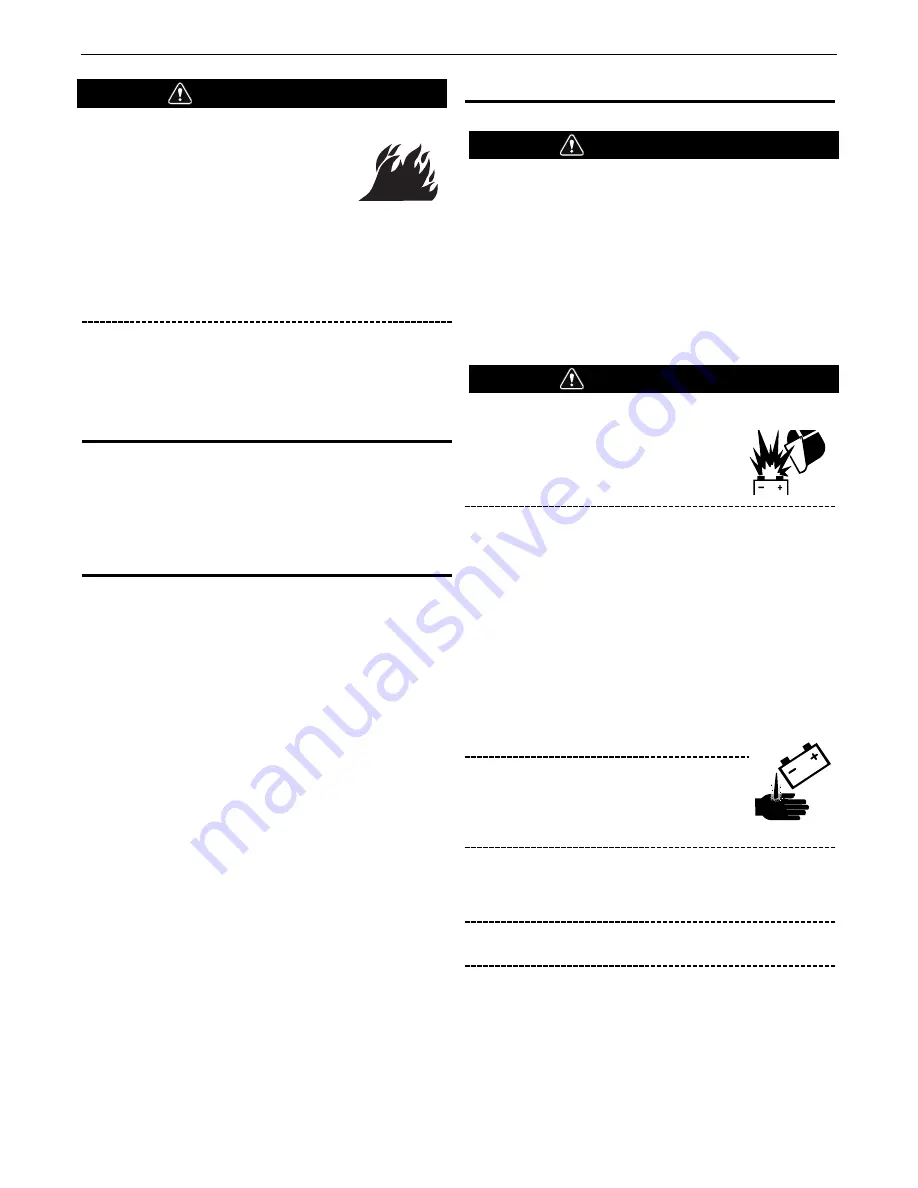
DIESEL FUEL can cause fire.

• 

Stop engine while fueling.

• 

Do not smoke when fueling.

• 

Keep sparks and flame away  from tank.

• 

Do not leave unattended while fueling.

• 

Wipe up spilled fuel and allow fumes to clear before
starting engine.

• 

Do not overfill tank, fuel expansion may cause overflow.

DIESEL FUEL ONLY

Fill the fuel tank with clean, fresh diesel fuel.  The capacity of the
fuel tank is 22.5 gallons (85.1 liters).  See engine Operator’s
Manual for specific fuel recommendations. 

Note:  Before starting the engine, be sure the fuel shutoff valve is
in the open position.  

ENGINE COOLING SYSTEM

The cooling system has been filled at the factory with a 50-50
mixture of ethylene glycol antifreeze and water.  Check the
radiator level and add a 50-50 solution as needed.  (See Engine
Manual or antifreeze container for alternate antifreeze recom-
mendation.)

ENGINE BREAK-IN PERIOD

Lincoln Electric selects high quality, heavy-duty industrial engines
for the portable welding machines we offer.  While it is normal to
see a small amount of crankcase oil consumption during initial
operation, excessive oil use, wet stacking (oil or tar like substance
at the exhaust port), or excessive smoke is not normal.

Larger machines with a capacity of 350 amperes and higher,
which are operated at low or no-load conditions for extended
periods of time are especially susceptible to the conditions
described above.  To accomplish successful engine break-in, most
diesel-powered equipment needs only to be run at a reasonably
heavy load within the rating of the welder for some period of time
during the engine’s early life.  However, if the welder is subjected
to extensive light loading, occasional moderate to heavy loading of
the engine may sometimes be necessary.  Caution must be
observed in correctly loading a diesel/generator unit.

1. Connect the welder output studs to a suitable resistive load

bank.  Note that any attempt to short the output studs by
connecting the welding leads together, direct shorting of the
output studs, or connecting the output leads to a length of
steel will result in catastrophic damage to the generator and
voids the warranty.

2.  Set the welder controls for an output current and voltage

within the welder rating and duty cycle.  Note that any
attempt to exceed the welder rating or duty cycle for any
period of time will result in catastrophic damage to the
generator and voids the warranty.

3.  Periodically shut off the engine and check the crankcase oil

level.

BATTERY CONNECTION

• 

Use caution as the electrolyte is a strong acid that can
burn skin and damage eyes.

• 

Remove and discard the insulating cap from the
negative battery terminal.  Attach and tighten negative
battery cable terminal.  

NOTE:  This machine is furnished with a wet charged battery; if
unused for several months, the battery may require a booster
charge.  Be careful to charge the battery with the correct polarity.
Make sure that the battery is level while charging.

Gases from battery can explode.

Keep sparks, flame and cigarettes away
from battery.

To prevent EXPLOSION when:

• 

INSTALLING A NEW BATTERY — disconnect negative
cable from old battery first and connect to new battery
last.

• 

CONNECTING A BATTERY CHARGER — remove
battery from welder by disconnecting negative cable
first, then positive cable and battery clamp. When
reinstalling, connect negative cable last. Keep well
ventilated.

• 

USING A BOOSTER — connect positive lead to battery
first then connect negative lead to negative battery lead
at the lower control panel support.

BATTERY ACID can burn eyes and skin.

• 

Wear gloves and eye protection and be
careful when working near battery.

• 

Follow instructions printed on battery.

IMPORTANT: To prevent ELECTRICAL DAMAGE WHEN:

a) Installing a new batterie. 

b) Using a booster. 

Use correct polarity — Negative Ground.

To prevent BATTERY BUCKLING, tighten the nuts on battery
until snug. DO NOT OVERTIGHTEN.

WARNING

WARNING

WARNING

Содержание SAE-400 SEVERE DUTY IM727

Страница 1: ...uthorized Service and Distributor Locator www lincolnelectric com locator IM10027 C Issue Date Aug 15 Lincoln Global Inc All Rights Reserved For use with machines having Code Numbers 11605 11807 11966 12311 Save for future reference Date Purchased Code ex 10859 Serial ex U1060512345 ...

Страница 2: ...the general area IN A LARGE ROOM OR OUTDOORS natural ventilation may be adequate if you keep your head out of the fumes See below USE NATURAL DRAFTS or fans to keep the fumes away from your face If you develop unusual symptoms see your supervisor Perhaps the welding atmosphere and ventilation system should be checked WEAR CORRECT EYE EAR BODY PROTECTION PROTECT your eyes and face with welding helm...

Страница 3: ...ty guards covers and devices in position and in good repair Keep hands hair clothing and tools away from V belts gears fans and all other moving parts when starting operating or repairing equipment 1 e In some cases it may be necessary to remove safety guards to perform required maintenance Remove guards only when necessary and replace them when the maintenance requiring their removal is complete ...

Страница 4: ...o ANSI Z87 I standards 4 b Use suitable clothing made from durable flame resistant material to protect your skin and that of your helpers from the arc rays 4 c Protect other nearby personnel with suitable non flammable screening and or warn them not to watch the arc nor expose themselves to the arc rays or to hot spatter or metal FUMES AND GASES CAN BE DANGEROUS 5 a Welding may produce fumes and g...

Страница 5: ...h lifting chains crane cables or other alternate circuits This can create fire hazards or overheat lifting chains or cables until they fail 6 h Also see item 1 c 6 I Read and follow NFPA 51B Standard for Fire Prevention During Welding Cutting and Other Hot Work available from NFPA 1 Batterymarch Park PO box 9101 Quincy Ma 022690 9101 6 j Do not use a welding power source for pipe thawing CYLINDER ...

Страница 6: ...MMENDED APPLICATIONS B 2 DESIGN FEATURES AND ADVANTAGES B 2 DUTY CYCLE B 2 ENGINE CONTROLS B 2 WELDER CONTROLS B 3 CURRENT CONTROL B 3 REMOTE CONTROL B 3 AUXILIARY POWER CONTROLS B 4 ENGINE OPERATION B 5 STARTING INSTRUCTIONS B 5 STOPPING THE ENGINE B 5 TYPICAL FUEL CONSUMPTION B 6 ACCESSORIES C 1 MAINTENANCE D 1 ROUTINE MAINTENANCE D 1 ENGINE AIR FILTER D 1 PERIODIC MAINTENANCE D 1 TROUBLESHOOTIN...

Страница 7: ...PUT VOLTS AT RATED AMPS 35 NEMA 500 AMPS 40 VOLTS 60 NEMA 500 AMPS 40 VOLTS 100 NEMA 400 AMPS 36 VOLTS 100 LINCOLN PLUS 400 AMPS 40 VOLTS OUTPUT WELDER AND GENERATOR WELDING RANGE OPEN CIRCUIT VOLTAGE AUXILIARY POWER 80 575 AMPS 97 MAX OCV 1800 RPM 115 230 VAC 3000 WATTS 60 HZ 100 DUTY CYCLE RECEPTACLES AND CIRCUIT BREAKERS RECEPTACLES AUXILIARY POWER CIRCUIT BREAKER 1 115VAC DUPLEX NEMA 5 20R GFC...

Страница 8: ...haust fumes are properly vented to an outside area DO NOT MOUNT OVER COMBUSTIBLE SURFACES Where there is a combustible surface directly under stationary or fixed electrical equipment that surface should be covered with a steel plate at least 06 1 6mm thick which should extend not less than 5 90 150mm beyond the equipment on all sides STACKING These machines cannot be stacked ANGLE OF OPERATION To ...

Страница 9: ...onditions 5 Proper preventative maintenance of trailer 6 Conformance with federal state and local laws 1 1 For highway use consult applicable federal state and local laws regarding specific requirements for use on public highways such as brakes lights fenders etc VEHICLE MOUNTING Improperly mounted concentrated loads may cause unstable vehicle handling and tires or other components to fail Only tr...

Страница 10: ...put studs to a suitable resistive load bank Note that any attempt to short the output studs by connecting the welding leads together direct shorting of the output studs or connecting the output leads to a length of steel will result in catastrophic damage to the generator and voids the warranty 2 Set the welder controls for an output current and voltage within the welder rating and duty cycle Note...

Страница 11: ...TABLE A 1 COMBINED LENGTH OF ELECTRODE AND WORK CABLES MACHINE GROUNDING Because this portable engine driven welder creates its own power it is not necessary to connect its frame to an earth ground unless the machine is connected to premises wiring home shop etc To prevent dangerous electric shock other equipment powered by this engine driven welder must a be grounded to the frame of the welder us...

Страница 12: ...actices FUMES AND GASES can be dangerous to your health Keep your head out of fumes Use enough ventilation or exhaust at the arc or both to keep the fumes and gases from your breathing zone and general area WELDING SPARKS can cause fire or explosion Do not weld near flammable material Do not weld on containers that have held flammable material MOVING PARTS can injure Keep away from moving parts Do...

Страница 13: ... oil pressure coolant temperature and battery charging ammeter Engine hour meter fuel gauge standard code 12311 Engine hour meter standard Code 11605 11807 11966 Extended range 22 5 gallon 85 1 L fuel tank DUTY CYCLE Duty cycle is the percentage of time the load is being applied in a 10 minute period For example a 60 duty cycle represents 6 minutes of load and 4 minutes of no load in a 10 minute p...

Страница 14: ... arc when welding vertical up or overhead CURRENT CONTROL Do not adjust the Current Control while welding because this can damage the control The Current Control dial is calibrated in amperes on three separate colored dials corresponding to the white black and red ranges of the Job Selector dial For example when the Job Selector is set on the black range the approximate welding current is indicate...

Страница 15: ...p removing voltage from the output of the receptacle If the GFCI is tripped see the MAINTENANCE section for detailed information on testing and resetting it The GFCI should be properly tested at least once every month The 115V auxiliary power receptacles should only be used with three wire grounded type plugs or approved double insulated tools with two wire plugs The current rating of any plug use...

Страница 16: ...ressure If no pressure shows within 30 seconds stop the engine and consult the engine operating manual To stop the engine turn the IGNITION switch to OFF 6 If the engine protection warning light comes on during cranking or after start up the IGNITION switch must be turned OFF to reset the engine protection system 7 Allow the engine to run at high idle speed for several minutes to warm the engine S...

Страница 17: ...perating scenarios is shown below SAE 400 PERKINS 1104A 44 LOW IDLE NO LOAD 1100 RPM 26 GAL HR 97 L HR HIGH IDLE NO LOAD 1800 RPM 68 GAL HR 2 56 L HR WELDING LOAD 400 AMPS 40 VOLTS 1 84 GAL HR 6 95 L HR WELDING LOAD 500 AMPS 40 VOLTS 2 38 GAL HR 9 02 L HR AUXILIARY POWER 3000VA 79 GAL HR 2 98 L HR ...

Страница 18: ...er designed for road 1 off road in plant and yard towing Trailer mounts directly to welder base Comes standard with a Duo Hitch a 2 Ball and Lunette Eye combination hitch Order K2636 1 Trailer K2639 1 Fender Light Kit K2640 1 Cable Storage Rack 1For highway use consult applicable federal state and local laws regarding possible requirements for brakes lights fenders etc Pipe Thawing with an arc wel...

Страница 19: ...very two months In particularly dirty locations this cleaning may be necessary once a week Use low pressure air to avoid driving dirt into the insulation 2 The current control reactor brushes are self lubricating and should not be greased Keep the contacts clean This control should be moved from maximum to minimum daily to prevent the controls from sticking 3 See the engine Instruction Manual for ...

Страница 20: ...d with a pressure radiator Keep the radiator cap tight to prevent loss of coolant Clean and flush the cooling system periodically to prevent clogging the passage and overheating the engine When antifreeze is needed always use the permanent type Fuel Pre Filter Water Separator Assembly When working on the fuel system Keep unguarded lights away do not smoke Do not spill fuel The SAE 400 is equipped ...

Страница 21: ...e the clean out plug GFCI Testing AND RESETTING Procedure The GFCI should be properly tested at least once every month or whenever it is tripped To properly test and reset the GFCI If the GFCI has tripped first carefully remove any load and check it for damage If the equipment has been shut down it must be restarted The equipment needs to be operating at high idle speed and any necessary adjustmen...

Страница 22: ...e machine is exhibiting Step 2 POSSIBLE CAUSE The second column labeled POSSIBLE CAUSE lists the obvious external possibilities that may contribute to the machine symptom Step 3 RECOMMENDED COURSE OF ACTION This column provides a course of action for the Possible Cause generally it states to contact your local Lincoln Authorized Field Service Facility If you do not understand or are unable to perf...

Страница 23: ...poor 5 Tighten all connections 6 Wrong grade of brushes may be installed on generator 6 Use only the recommended Lincoln brushes 7 Field rheostat may be making poor contact and overheating 7 Inspect and clean rheostat 8 Current Control may not be operating properly 8 Check for loose or missing set screw in control handles 9 Current Control brush holder contact springs may be worn out or missing Co...

Страница 24: ...tput with ammeter 3 Polarity may be wrong 3 Check polarity Try reversing polarity or try an electrode of the opposite polarity Welding current too great or too small compared to indication on the dial 1 Current Control shaft and handle may have turned slightly in the insulated bushing of the current control brush holder caused by turning handle too hard against one of the stops 1 With current cont...

Страница 25: ... Assembly AR 3 P 909 E Generator Alternator Assembly AR 4 P 909 F Lower Control Panel Assembly AR 5 P 909 G Control Panel Assembly AR 6 P 909 H Left Gas Tank Rail Output Panel AR 7 P 909 J Remote Control AR 8 P 909 K Generator Brush Holder AR Index of Sub Assemblies 12311 SAE 400 Perkins 12311 1 Printed 08 17 2015 at 08 38 18 Produced by Enigma ...

Страница 26: ...4 1 2 13BR HJN 1 9SS17472 1 REED SWITCH LEAD ASBLY 1 9SL2286 272 LEAD 1 9SS9262 4 PLAIN WASHER 2 9SE106A 4 LOCKWASHER 1 9SCF000067 3 8 16HN 1 9SS27368 6 LOGO DECAL 2 9ST13086 62 DECAL WARNING 2 9SM16679 DECAL WARNING 1 9ST13086 26 DECAL 1 9ST13260 4 DECAL EARTH GROUND CONN 1 9ST11030 DECAL DOOROPEN CLOSE 2 9SM16197 DECAL WARNING 1 9SM17238 INSTRUCTION TAG 1 9SS25896 DECAL WARNING 1 9SS26005 SERVIC...

Страница 27: ...KEY PART NUMBER DESCRIPTION QTY 9SS29243 DECAL ENGINE CIRCUIT BREAKER 1 Miscellaneous Items SAE 400 Perkins 12311 3 Printed 08 17 2015 at 08 38 18 Produced by Enigma ...

Страница 28: ...No Image Miscellaneous Items 4 SAE 400 Perkins 12311 Printed 08 17 2015 at 08 38 18 Produced by Enigma ...

Страница 29: ... 5 16 18HN 2 10 9SM9399 4 Battery 2 9ST14654 CAP PLASTIC 2 9SS16931 4 BATTERY CLAMP BRACKET 1 9ST8818 3 BATTERY CLAMP HOOK 2 9SE106A 3 LOCKWASHER 2 9SCF000029 5 16 18HN 2 11 9SM8237 13 REAR SUPPORT ASBLY 1 9ST9860 4 LOCKWASHER 4 9SS9225 28 THREAD FORMING SCREW 4 15 9SM8889 3 LIFT BALE ASBLY 1 9ST8833 24 HEX HD CAP SCREW 4 9SE106A 15 LOCKWASHER 1 9SCF000027 1 2 13HN 1 17 9SS12934 2 COVER SEAL 1 18 ...

Страница 30: ... 5 RADIATOR SHELL ASBLY 1 9SL3102 9 RADIATOR 1 9SM8003 RADIATOR CAP COVER ASBLY 1 9SS8025 12 SELF TAPPING SCREW 2 9SL12191 1 SHROUD RADIATOR 1 9SS29451 ISOLATION MOUNT 4 9SS9225 76 SELF TAPPING SCREW 8 9SS9262 187 PLAIN WASHER SS 4 9ST9447 53 SCREW 1 4 20 X 1 50 SOCKET HEAD 4 9SS9262 69 PLAIN WASHER 8 9SE106A 2 LOCKWASHER 4 9SCF000017 1 4 20HN 4 9SM20542 1 FAN GUARD PUMP SIDE 1 9SM20811 1 FAN GUAR...

Страница 31: ... 39 9ST8818 ROOF HOOK 2 9ST9187 LOCKNUT 2 9ST15154 DOOR BUMPER 8 41 9SL3319 C DOOR 4 42 9SS20295 DOOR HINGE PIN 8 9SS9776 62 RETAINING RING 1 9SS21463 DOOR BUMPER 1 9SS9262 98 PLAIN WASHER 1 9SM8834 1 RIVET 1 9ST10982 7 SPEED CLIP 1 9SS10656 1 DOOR HOOK ASBLY 4 9ST10878 WASHER 4 9SS8025 92 SELF TAPPING SCREW 8 9SS10656 2 DOOR HOOK ASBLY 4 9ST10878 WASHER 4 9SS8025 92 SELF TAPPING SCREW 8 54 9SS254...

Страница 32: ...9 29 10 24X 38RHS FULL SS 1 9SS9262 174 PLAIN WASHER SS 2 9SE106A 22 WASHER 10 LOCK SS 1 9SCF000393 10 24SS HN 1 9SM18959 2 BREAKER RECEPTACLE GUARD ASBLY 1 9SS9225 68 THREAD FORMING SCREW CUTTING 2 Final Assembly 8 SAE 400 Perkins 12311 Printed 08 17 2015 at 08 38 18 Produced by Enigma ...

Страница 33: ...P 909 C jpg Final Assembly SAE 400 Perkins 12311 9 Printed 08 17 2015 at 08 38 18 Produced by Enigma ...

Страница 34: ...UEL SHUT OFF 1 9ST10642 91 FLUX TUBE 1 9ST10642 228 FLEX TUBE 1 7 9SS17026 3 OIL PRESSURE SENDER SWITCH 1 9SS24464 2 PIPE ADAPTOR 1 9ST14815 6 METRIC HEX NUT M4 X 0 7 2 8 9SL12426 1 MUFFLER 1 9SM21158 IDLER SOLENOID ASBLY 1 9SS20140 8 SOLENOID ASSEMBLY 1 9SM20527 1 IDLER SOLENOID BRACKET 1 9ST11525 5 SPEED NUT1 4 20 2 9SS9225 66 SELF TAPPING SCREW 2 9SE106A 2 LOCKWASHER 1 9SS22070 IN LINE SWIVEL 1...

Страница 35: ... CLAMP 1 9SS10888 29 HOSE CLAMP 1 24 9SL12350 LOWER RADIATOR HOSE 1 9SS10888 8 HOSE CLAMP 1 9SS10888 33 HOSE CLAMP 1 25 9SM17494 2 FILTER ASSEMBLY 1 9SM21584 B FUEL PRE FILTER WATER ELEMENT 1 9ST14731 4 METRIC HEX HD SCREW M8 X1 25 2 9SS9262 121 PLAIN WASHER 2 9SE106A 3 LOCKWASHER 2 26 9SS25162 SWITCH WATER 1 9SS25992 OIL FILTER SPACER 1 9ST14731 3 METRIC HEX HD SCREW M8 X1 25 2 9SS26001 GASKET 1 ...

Страница 36: ...P 909 D jpg Engine Assembly 12 SAE 400 Perkins 12311 Printed 08 17 2015 at 08 38 18 Produced by Enigma ...

Страница 37: ...9SM9300 122 BEARING310DOUBLE SYNTHETIC SEAL 1 6 9SL6795 1 END BRACKET MACHINING 1 9SS10780 4 PIPE PLUG 1 9SCF000277 1 2 13X1 75HHCS 1 25 GR2 4 7 9SM13641 4 M13641 4 ROTOR ASBLY 1 8 9SM16158 BRUSH BRUSH HOLDER ASBLY 1 9SG2114 BRUSH HOLDER CARTRIDGE 1 9SS19480 BRUSH ASBLY 2 9SM16157 BRUSH ASBLY RETAINER 1 9SM19896 BRUSH HOLDER BRACKET SS 1 9SCF000014 1 4 20X 75HHCS 2 9SS9262 23 PLAIN WASHER 2 9SE106...

Страница 38: ...TURE SLEEVE COLLAR 1 14 9SM13686 BOTTOM EXCITER COVER 1 9ST9860 6 LOCKWASHER 4 9SS9225 8 THREAD FORMING SCREW ROLLING 4 15 9SCF000067 3 8 16HN 1 Generator Alternator Assembly 14 SAE 400 Perkins 12311 Printed 08 17 2015 at 08 38 18 Produced by Enigma ...

Страница 39: ...P 909 E jpg Generator Alternator Assembly SAE 400 Perkins 12311 15 Printed 08 17 2015 at 08 38 18 Produced by Enigma ...

Страница 40: ...PTACLE 1 9SS9225 63 THREAD FORMING SCREW CUTTING 4 9ST11525 1 SPEED NUT 10 24 2 9SS22061 4 SEALING BOOT 1 13 9SS13146 1 START BUTTON 1 14 9ST10800 55 TOGGLE SWITCH 1 9SS22061 4 SEALING BOOT 1 15 9SS9225 36 THREAD FORMING SCREW CUTTING 1 9ST9695 1 LOCKWASHER 1 9SCF000010 10 24HN 4 20 9SL12400 3V1 IDLER ENGINE SHUTDOWN PC BD ASBLY 1 9SCF000149 10 24X1 25RHS 4 9SS9262 27 PLAIN WASHER 4 9SE106A 1 LOCK...

Страница 41: ...5 63 THREAD FORMING SCREW CUTTING 4 9SM22328 RECEPTACLE GUARD 1 9SS9225 63 THREAD FORMING SCREW CUTTING 4 9SS26843 1 GFCI REWORK 1 9SS28464 GFCI COVER 1 9SL13286 GFCI HOUSING 1 9SS27167 MOUNTING BRACKET 1 9SS24738 3 THERMOPLASTIC SCREW 2 Lower Control Panel Assembly SAE 400 Perkins 12311 17 Printed 08 17 2015 at 08 38 18 Produced by Enigma ...

Страница 42: ...P 909 F jpg Lower Control Panel Assembly 18 SAE 400 Perkins 12311 Printed 08 17 2015 at 08 38 18 Produced by Enigma ...

Страница 43: ... 1 LOCKWASHER 1 9SCF000061 SCREW 10 24X 375RHS 4 9ST7494 BRUSH CONTACT SPRING ASBLY 4 9ST8218 SHAFT 1 9ST8219 INSULATING TUBE 1 9SCF000062 5 16 18X1 00HHCS 2 11 9SS7297 REACTOR SPRING CLIP 1 12 9SS9262 41 PLAIN WASHER 1 13 9ST8236 SPRING 1 14 9SL2036 B REACTOR 1 9SS9225 8 THREAD FORMING SCREW ROLLING 4 15 9ST8280 RESISTOR WIREWOUND 1 9SCF000045 10 24X5 00RHS 1 9SE106A 1 LOCKWASHER 1 9SCF000010 10 ...

Страница 44: ...TACLE DUPLEX 1 24 9ST10576 INSULATION 1 9ST12563 12 LEAD CLAMP 1 9SS8025 22 SELF TAPPING SCREW 2 25 9ST12287 22 CIRCUIT BREAKER 15A 1 27 9ST12287 31 CIRCUIT BREAKER 20A250VAC32VDC 1 9SS22061 1 CIRCUIT BREAKER BOOT 2 9SM20585 3 CIRCUIT BREAKER 2 POLE 1 9SS24911 2 COVER CIRCUIT BREAKER 2 POLE 1 9ST10082 30 SEMS SCREW 4 9ST4291 A LOCKWASHER 4 9SS14165 463 RECEPTACLE LEAD ASBLY 1 34 9SS26606 DECAL SPA...

Страница 45: ...P 909 G jpg Control Panel Assembly SAE 400 Perkins 12311 21 Printed 08 17 2015 at 08 38 18 Produced by Enigma ...

Страница 46: ... 25HHCS 2 9SE106A 5 LOCKWASHER 2 9SCF000027 1 2 13HN 2 9SS9262 1 PLAIN WASHER 1 9 9SCF000020 1 2 13X 75HHCS 1 9SCF000344 HEX HD SCREW 1 9SS9262 1 PLAIN WASHER 1 9SE106A 15 LOCKWASHER 1 12 9ST3960 FLANGE NUT 2 13 9SS25371 DECALELECTRODE 1 14 9SS25372 DECALTO WORK 1 Left Gas Tank Rail Output Panel 22 SAE 400 Perkins 12311 Printed 08 17 2015 at 08 38 18 Produced by Enigma ...

Страница 47: ...P 909 H jpg Left Gas Tank Rail Output Panel SAE 400 Perkins 12311 23 Printed 08 17 2015 at 08 38 18 Produced by Enigma ...

Страница 48: ...NAMEPLATE REMOTE CONTROL 1 9SS9225 30 THREAD FORMING SCREW CUTTING 1 9ST9695 1 LOCKWASHER 1 9SCF000010 10 24HN 3 9 9ST9639 2 BOX CONNECTOR 1 10 9SS21007 CABLE ASBLY 1 9SCF000102 8 32X 50BR RHS 6 9SCF000103 8 32BR HN 1 11 9SM17285 RESISTOR BANK ASBLY 1 9SS21009 RESISTOR MTG BRKT 2 9SS10404 22 RESISTOR WIREWOUND 3 9SCF000045 10 24X5 00RHS 3 9ST4479 A INSULATING WASHER 3 9SE106A 1 LOCKWASHER 3 9SCF00...

Страница 49: ...P 909 J jpg Remote Control SAE 400 Perkins 12311 25 Printed 08 17 2015 at 08 38 18 Produced by Enigma ...

Страница 50: ...OLDER STUD INSULATION 1 6 9ST9020 PLAIN WASHER 1 7 9SM6963 6 BRUSH HOLDER STUD 1 8 9SM6304 2B RETAINER 1 13 9SE106A 3 LOCKWASHER 2 14 9SCF000040 5 16 18X 75HHCS 2 11 9ST8495 BRUSH HOLDER SPRING CLIP ASBLY 2 12 9ST8241 Brush Holder Spring Clip 2 13 9SE106A 3 LOCKWASHER 2 14 9SCF000040 5 16 18X 75HHCS 2 Generator Brush Holder 26 SAE 400 Perkins 12311 Printed 08 17 2015 at 08 38 18 Produced by Enigma...

Страница 51: ...P 909 K jpg Generator Brush Holder SAE 400 Perkins 12311 27 Printed 08 17 2015 at 08 38 18 Produced by Enigma ...

Страница 52: ...SAE 400 NOTE This diagram is for reference only It may not be accurate for all machines covered by this manual The specific diagram for a particular code is past ed inside the machine on one of the enclosure panels ...

Страница 53: ...SAE 400 NOTE This diagram is for reference only It may not be accurate for all machines covered by this manual The specific diagram for a particular code is past ed inside the machine on one of the enclosure panels ...

Страница 54: ...D3 115V 16A 1 PHASE YELLOW L 821A GND AA GND C 4C 202A 41B 6B 7B 4D 6C 7C SILVER TERMINAL LINE LOAD GFCI HOT WHITE 238 844 844A 238 5L 5S 5J 212B 212A 4 1 8 5 4 1 8 5 5K 212 5K 12V INSULATED STUD ON CONTROL PANEL FUEL LEVEL SENSOR 4 1 8 5 FUEL HOUR METER LEDS J52 GND D GND E 60A 54 55 57 53 50 50B 51A 50A 50A 50B 52 GND B GND C SWITCH G WK SENSOR PULL COIL HOLD COIL RED WHT FUEL PUMP IDLER SWITCH ...

Страница 55: ... A 81 HOLES N B 69 HOLES 28 00 22 00 22 14 24 50 27 12 6 00 39 69 47 95 23 00 26 00 38 50 63 06 50 13 21 00 44 00 8 90 44 50 69 75 8 12 77 00 3 00 81 25 88 83 00 CENTER OF GRAVITY WITH OIL AND WATER IN ENGINE BUT NO FUEL N A N A N B N B ...

Страница 56: ...e Discard the cover plate and keep the screws for later use 6 Insert the sealing boot through the RCD cut out in the lower control panel Then insert the RCD Mount the RCD by using the RCD bracket set aside in step 3 and the screws set aside in step 2 7 Mount the RCD cover box to the lower control panel using the screws set aside in step 3 Make sure the sleeving that is covering the leads is insert...

Страница 57: ...IGURE 2 RCD SEALING BOOT RCD Mounting Strap 2 POLE RCD Sleeving FIGURE 3 RCD Cover Box Sleeving Route out of lower corner of RCD cover box to upper control panel RED 6A RED 7A BLACK 6C BLACK 7C FIGURE 1 RCD Cover Plate Lower Control Panel 230V Euro Receptacle ...

Страница 58: ...parts or electrode with skin or wet clothing l Insulate yourself from work and ground l No toque las partes o los electrodos bajo carga con la piel o ropa moja da l Aislese del trabajo y de la tierra l Ne laissez ni la peau ni des vête ments mouillés entrer en contact avec des pièces sous tension l Isolez vous du travail et de la terre l Berühren Sie keine stromführenden Teile oder Elektroden mit ...

Страница 59: ... und Entlüftung des Arbeitsplatzes l Mantenha seu rosto da fumaça l Use ventilação e exhaustão para remover fumo da zona respiratória l Turn power off before servicing l Desconectar el cable de ali mentación de poder de la máquina antes de iniciar cualquier servicio l Débranchez le courant avant l entre tien l Strom vor Wartungsarbeiten abschalten Netzstrom völlig öff nen Maschine anhalten l Não o...

Страница 60: ...stomer s particular purpose with respect to such information or advice As a matter of practical consideration we also cannot assume any respon sibility for updating or correcting any such information or advice once it has been given nor does the provision of information or advice create expand or alter any warranty with respect to the sale of our products Lincoln Electric is a responsive manufactu...

Отзывы: