


Page 20
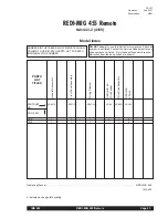
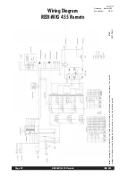
REDI-MIG 455 Remote
IMA 603
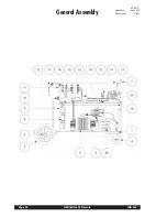
Section 7 - ACCESSORIES
°
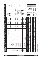
Drive Rolls for mild steel, stainless steel and aluminium for
solid wires as well as for flux cored wires. See your nearest
Lincoln distributor for details.
°
1.2mm Aluminium Welding Kit complete with 2 x 0.9mm,
1.2mm U-groove drive rolls, 0.9-1.2mm Teflon torch liner,
packet of 10 X 1.2mm contact tips, Teflon inlet and outlet
guides (KA1440-3).
°
1.2mm Flux Cored, Gas and Gasless Welding Kit,
complete with 2 x 0.9, 1.2mm knurled drive rolls, 0.9-
1.2mm torch liner and packet of 10 x 1.2mm contact tips
(KA1441-3).
°
Innershield (Self Shielded or Gasless Wire) Welding Gun
with Euro connect fitting for best results with gasless wires
(KA1325).
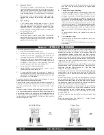
Section 8 - GROUND TEST PROCEDURE
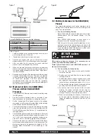
Changing Settings for Motor Acceleration
If Motor Acceleration needs to be altered from factory setting,
because of the welding procedure being used, locate the PCB in
the REDI-MIG 4D Remote Wire Feeder.
On the PCB there is a trimmer labelled ‘Rampa’, this trimmer
controls the acceleration rate of the drive motor from stationary to
the set wire feed speed. Maximum acceleration when fully
counter-clockwise to minimum acceleration when fully clockwise.
This is particularly important when welding aluminium wire. The
factory setting is fully clockwise.
Procedure for Replacing PC Boards
Before replacing a PC board suspected of being defective,
visually inspect the PC board in question for any visible damage
to any of its components and conductors on the back of the board.
1.
If there is no visible damage to the PC board, install a new
one and see if this remedies the problem. If the problem is
remedied, reinstall the original PC board to see if the
problem still exists. If the problem no longer exists with the
old PC board:
a. Check the PC board harness connector pins for
corrosion, contamination, or looseness.
b. Check leads in the plug harness for loose or intermittent
connection.
2.
If PC board is visibly damaged, before possibly subjecting
the new PC board to the same cause of failure, check for
possible shorts, opens or grounds caused by:
a. Damaged lead insulation.
b. Poor lead termination, such as a poor contact or a short
to adjacent connection or surface.
c. Shorted or open motor leads, or other external leads.
d. Foreign matter or interference behind the PC board.
3.
If PC board is visibly damaged, inspect for cause, then
remedy before installing a replacement PC board.
6.5 Liner Removal, Installation and Trimming
Instructions for REDI-MIG 4 Torch
Note: The variation in cable lengths prevents the inter-
changeability of liners between guns. Once a liner has
been cut for a particular gun, it should not be installed in
another gun unless it can meet the liner cutoff length
requirement.
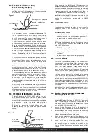
1.
Remove the gas nozzle and nozzle insulator, (if used), to
locate the set screw in the gas diffuser which is used to
hold the old liner in place. Loosen the set screw with an
Allen key.
2.
Remove the gas diffuser from the gun tube.
3.
Lay the gun and cable out straight on a flat surface.
Loosen the liner nut cap located in the brass connector at
the feeder end of the cable and pull the liner out of the
cable.
4.
Insert a new untrimmed liner into the connector end of the
cable.
5.
Fully seat the liner bushing into the Euro connector.
Tighten the liner nut cap on the brass cable connector. The
gas diffuser, at this time, should not be installed onto the
end of the gun tube.
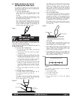
6.
With the gas diffuser still removed from the gun tube, be
sure the cable is straight, and then trim the liner to length.
Remove any burrs from the end of the liner.
7.
Screw the gas diffuser onto the end of the gun tube and
securely tighten. Be sure the gas diffuser is correct for the
liner being used.
8.
Tighten the set screw in the side of the gas diffuser against
the cable liner using an Allen key. Do not overtighten.
Note: This procedure is for ‘machines as built’ many
modifications could have taken place over the life of a particular
machine, so details of this procedure may need to be ‘adjusted’ to
suit these modifications.
For prompt service contact your local Lincoln Field Service Shop.
The insulation resistance values listed below are from Australian
Standard AS1966.1.
1)
Disconnect input cable from power outlet.
2)
Disconnect all output cables (control & weld).
3)
Remove the roof panel.
4)
Jumper the three (3) AC terminals and the (+) & (-)
terminals of the three phase bridge rectifier (A total of five
(5) places).
5)
Unplug digital meter PCB plug.
6)
Switch the fine control rotary switch to position ‘a’ & switch
the coarse control rotary switch to position ‘A’.
7)
Primary test: Connect one lead of the mega tester to the
frame of the machine and the other lead to each of the
three (3) input conductors and to the main transformer
primary leads L1A, L2A & L3A. Apply the test(s).
8)
Welding circuit test: Connect one lead of the mega tester
to the frame of the machine and the other lead to the
positive output stud. Apply the test. (Min resistance 1M
Ω
).
9)
Welding circuit to primary test: Connect one lead of the
mega tester to the positive output stud and the other lead
to each of the three (3) input conductors and to the main
transformer primary leads L1A, L2A & L3A. Apply the test.
(Min resistance 10M
Ω
).
10)
Transformer thermostat test: Connect one lead of the
mega tester to the frame of the machine and the other lead
to the positive output stud. Apply the test.(Min resistance
1M
Ω
).
11)
Remove all jumper leads.
12)
Refit the roof panel.
ELECTRIC SHOCK
can kill
WARNING
This procedure is only suitable for applications using DC
mega testers up to 500V.


