Lincoln Electric REDI-MIG 455 Remote Скачать руководство пользователя страница 14

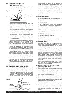
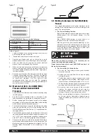
5.2 The Self-Shielded (Gasless) 

FCAW Welding Arc (DC-)

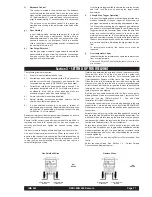
Figure 1 illustrates the action taking place in the self
shielded gasless FCAW welding arc. It closely resembles
what is actually seen while welding.

The “arc stream” is seen in the middle of the picture. This
is the electric arc created by the electric current flowing
through the space between the end of the wire electrode
and the base metal. The temperature of this arc is about
3300°C, which is more than enough to melt metal.

The arc is very bright, as well as hot, and cannot be looked
at with the naked eye without risking painful injury. The very
dark lens, specifically designed for arc welding must be
used with the hand or face shield whenever viewing the arc.

The arc melts the base metal and actually digs into it much
as water through a nozzle on a garden hose digs into the
earth. The molten metal forms a molten pool or crater and
tends to flow away from the arc. As it moves away from the
arc, it cools and solidifies.

The function of the cored wire electrode is much more than
simply to carry current to the arc. The wire core is
composed of fluxes and/or alloying ingredients around
which a steel sheath has been formed. It is simply a stick
electrode turned inside out in a continuous wire form.

The cored wire melts in the arc and tiny droplets of molten
metal shoot across the arc into the molten pool. The wire
sheath provides additional filler metal for the joint to fill the
groove or gap between the two pieces of base metal.

The core materials also melt or burn in the arc and perform
several functions. They make the arc steadier, provide a
shield of smoke-like gas around the arc to keep oxygen
and nitrogen in the air away from the molten metal, and
provide a flux for the molten pool. The flux picks up
impurities and forms the protective slag on top of the weld
during cooling.

After running a weld bead, the slag may be removed with a
chipping hammer and wire brush. This improves
appearance and allows for inspection of the finished weld.

Machine size and output characteristics limit the size and
type of wire electrode which can be used.

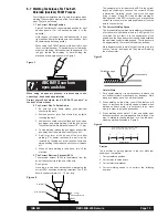
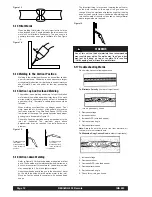
5.3 The GMAW (MIG) Welding Arc (DC+)

Figure 2 illustrates the GMAW (MIG) welding arc. Solid
wire does not contain fluxes or ingredients to form its own
shielding and no slag forms to protect the molten weld
metal. For this reason, a continuous even flow of shielding
gas is needed to protect the molten weld metal from
atmospheric contaminants such as oxygen and nitrogen.
Shielding gas is supplied through the gun and cable
assembly, through the gas nozzle and into the welding
zone.

When comparing the GMAW and FCAW processes, you
can see that the principal difference between the two lies in
the type of shielding used. GMAW uses gas for shielding,
thus we have Gas Metal Arc Welding. FCAW uses the
melting or burning of the core ingredients for shielding, and
is thus termed Self-Shielded Flux Cored Arc Welding.

Gas Metal Arc Welding (MIG) is capable of welding a wide
range of mild steels in all positions, however, more skill is
required for out-of-position welding with the GMAW
process.

5.4 Process Selection

By gaining knowledge of the differences between the two
processes, you will be able to select the best process for
the job you have at hand. In selecting a process, you
should consider:

For GMAW (MIG) Process

1. Can I afford the extra expense, space, and lack of

portability required for gas cylinders and gas supply?

2. Do I require clean, finished-looking welds?

If you have answered yes to all the above questions
GMAW may be the process for you. If you have answered
no to any of the above questions, then you should consider
using the FCAW process.

For FCAW (Innershield) Process

1. Do I want simplicity and portability?

2. Will welding be performed outdoors or under windy

conditions?

3. Do I require good all position welding capability?

5.5 Common Metals

Most metals found around the farm, small shop or home
are low carbon steel, sometimes referred to as mild steel.
Typical items made with this type of steel include most
sheet metal, plate, pipe and rolled shapes such as
channels and angle irons. This type of steel can usually be
easily welded without special precautions. Some steels,
however, contain higher carbon levels or other alloys and
are more difficult to weld. Basically, if a magnet sticks to the
metal and you can easily cut the metal with a file, chances
are good that the metal is mild steel and that you will be
able to weld the material. In addition, aluminum can be
welded using the an aluminum welding kit (KA1440-3). For
further information on identifying various types of steels
and other metals, and for proper procedures for welding
them, we suggest you purchase a copy of “New Lessons in
Arc Welding”.

Regardless of the type of metal being welded, in order to
get a quality weld, it is important that the metal is free of oil,
paint, rust or other contaminants.

5.6 Machine Set up for the Self-Shielded

(Gasless) FCAW Process

1.

Ensure the machine has the correct drive roll and parts (all
required parts for cored wire welding are supplied in the
Innershield (Gasless) Welding Kit KA1441-3). Best results
using self-shielded flux cored wires are obtained when
using a gun specially designed for these types of wires
such as the KA1325 Innershield Gun.

2.

See the Welding Procedure Guide on the inside of wire
feed section door for information on setting the controls.

3.

Set the “Voltage” and “Wire Speed” controls to the settings
suggested on the Welding Procedure Guide for the welding
wire and base metal thickness being used.

4.

Check that the polarity is correct for the welding wire being
used. See Section 1.5 for instructions on changing polarity.

5.

Connect work clamp to metal to be welded. Work clamp
must make good electrical contact to the work piece. The
work piece must also be grounded as stated in the “Arc
Welding Safety Precautions” at the beginning of this
manual.

Burning of core materials
inside wire electrode
results in shield of gas.

Arc Stream

Cored Wire

Protective Slag

Weld Metal

Figure 1

Gas nozzle

Shielding gas

Solid wire
electrode

Figure 2

Page 14

REDI-MIG 455 Remote

IMA 603

Содержание REDI-MIG 455 Remote

Страница 1: ...tric welders are designed and built with safety in mind However your overall safety can be increased by proper installation and thoughtful operation on your part Read and observe the general safety precautions on page 2 and follow specific installation and operating instructions included in this manual Most importantly think before you act and be careful IMA 603 OPERATING MANUAL Part No Code Descr...

Страница 2: ...and understand the manufacturer s instructions for this equipment and the consumables to be used including the material safety data sheet MSDS and follow your employer s safety practices e Also see Item 7b 3 a Use a shield with the proper filter and cover plates to protect your eyes from sparks and the rays of the arc when welding or observing open arc welding Headshield and filter lens should con...

Страница 3: ...ety guards to perform required maintenance Remove guards only when necessary and replace them when the maintenance requiring their removal is complete Always use the greatest care when working near moving parts f Do not put your hands near the engine fan Do not attempt to override the governor or idler by pushing on the throttle control rods while the engine is running g To prevent accidentally st...

Страница 4: ...elding can interfere with a pacemakers function Generally the interference does not permanently damage the pacemaker Once the wearer leaves the arc welding environment or stops welding the pacemaker returns to normal functioning The welding arc has little or no effect on the operation of some pacemakers especially designs that are bi polar or designed to filter out such interference For a welder o...

Страница 5: ...welding or other activities are to be carried out The size of the surrounding area to be considered will depend on the structure of the building and other activities that are taking place The surrounding area may extend beyond the boundaries of the premises Methods of Reducing Emissions Mains Supply Welding equipment should be connected to the mains supply according to the manufacturer s recommend...

Страница 6: ...erence This information can be found on your machine nameplate Model Name Number _______________________________________________ Code Serial Number ________________________________________________ Date of Purchase ____________________________________________________ Read this Operator s Manual completely before attempting to use this equipment Save this manual and keep it handy for quick reference...

Страница 7: ...he Self Shielded Gasless FCAW Process 15 5 8 Machine Set Up for the GMAW MIG and Gas Shielded FCAW Processes 16 5 9 Welding Techniques for the GMAW MIG Process 16 5 10 Joint Types and Positions 17 5 11 Butt Welds 17 5 12 Penetration 17 5 13 Fillet Welds 18 5 14 Welding in the Vertical Position 18 5 15 Vertical Up and Overhead Welding 18 5 16 Vertical Down Welding 18 5 17 Troubleshooting Welds 18 S...

Страница 8: ...or disconnecting cables or other equipment WARNING HIGH VOLTAGE can kill Only qualified personnel should install or service this equipment PRODUCT DESCRIPTION The REDI MIG 455 Remote offers a remote wire feeder and a separate Constant Voltage DC arc welding machine It combines a solid state power source with electronically controlled wire feeding equipment Excellent arc characteristics are provide...

Страница 9: ... gun and cable other than the supplied gun is to be used it must conform to standard European style connector specifications See diagram under The gun trigger switch must be capable of switching 10 milliamps at 60 volts DC resistive 1 5 Output Polarity Connection The REDI MIG 4D is connected to the REDI MIG 455 Remote power source via a control electrode gas cable assembly The electrode cable is c...

Страница 10: ...wire feed motor on and off depending upon the trigger mode setting The wire feed motor is dynamically braked to minimise wire overrun after welding has ceased Welding voltage is available immediately the gun trigger is operated When welding is stopped there is a delay to allow the electrode to burn back slightly and prevent sticking in the crater See Burnback Control 2 2 f e Inductance Settings Th...

Страница 11: ...th suitable lens gloves etc 6 If a gas shielded process is to be used a cylinder of appropriate gas is required Regulator flowmeter and hose are supplied If gas shielding is required connect the gas per Section 1 3 of this manual Remember that gas cylinders may explode if damaged so ensure that all gas cylinders are securely mounted Ensure that the correct type and size wire feed rolls are fitted ...

Страница 12: ...m GM226 Liner Teflon 0 9 1 2mm GM230 Liner 0 9 1 2mm GM226 Drive Ro ll 1 2 1 6mm GM231 Aluminium Feeding Kit KA1440 3 Flux Cored Feeding Kit KA1441 3 PLATE THICKNESS 0 9mm 1 6mm 3 0mm 5 0mm 8 0mm 21 gauge 16 gauge 10 gauge 6 gauge 1 gauge PROCESS WELDING WIRE SHIELDING GAS 0 032 1 16 0 134 0 203 0 300 Recommended Wire 0 9mm Dia MIG Solid Steel Wire Argon CO 2 blend Aa 3 Af 5 Bb 7 Bi 12 Cb 16 DC Li...

Страница 13: ...ble for the wire to arc to the case Any wire overrun should be avoided WARNING Part No Size mm Use with AS4449 9 0 6 0 8 Solid Wire AS4449 11 0 8 0 9 Solid Wire AS4449 8 0 9 1 2 Solid Wire AS4449 2 1 0 1 2 Solid Wire AS4449 5 0 8 1 0 Aluminium Wire AS4449 12 0 9 1 2 Aluminium Wire AS4449 6 1 2 1 6 Aluminium Wire AS4449 3 0 8 1 0 Cored Wire AS4449 13 0 9 1 2 Cored Wire AS4449 4 1 2 1 6 Cored Wire A...

Страница 14: ...e of welding a wide range of mild steels in all positions however more skill is required for out of position welding with the GMAW process 5 4 Process Selection By gaining knowledge of the differences between the two processes you will be able to select the best process for the job you have at hand In selecting a process you should consider For GMAW MIG Process 1 Can I afford the extra expense spa...

Страница 15: ... has been established maintaining the correct ESO becomes extremely important The ESO should be approximately 10 12 mm long The easiest way to tell whether the ESO is the correct length is by listening to its sound The correct ESO has a distinctive crackling sound very much like eggs frying in a pan A long ESO has a hollow blowing or hissing sound If the ESO is too short you may stick the contact ...

Страница 16: ...p must make good electrical contact to the work piece The work piece must also be grounded as stated in the Arc Welding Safety Precautions at the beginning of this manual 5 9 Welding Techniques for the GMAW MIG Process Four simple manipulations are of prime importance when welding With complete mastery of the four welding will be easy They are as follows 1 The Correct Welding Position Figure 8 ill...

Страница 17: ...ct face and eyes 3 Depress gun trigger hold gun so contact tip to work distance is about 10 12 mm and the gun is at proper angle 4 After you strike the arc practice the correct electrical stickout Learn to distinguish it by its sound 5 When you are sure that you can hold the correct electrical stickout with a smooth crackling arc start moving Look at the molten puddle constantly 6 Run beads on a f...

Страница 18: ...rtical down welds may be applied to 4 0 mm and lighter material Use stringer beads and tip the gun in the direction of travel so the arc force helps hold the molten metal in the joint Move as fast as possible consistent with desired bead shape The important thing is to continue lowering the entire arm as the weld is made so the angle of the gun does not change Move the electrode wire fast enough t...

Страница 19: ...rmostats automatically reset when the temperature reaches a safe operating level The fan will stay on when the machines welding and feeding are disabled during thermostatic overtemperature protection 6 2 Gun and Cable Maintenance Cable Cleaning Clean cable liner after using approximately 150kg of electrode Remove the cable from the wire feeder and lay it out straight on the floor Remove the contac...

Страница 20: ...her gun unless it can meet the liner cutoff length requirement 1 Remove the gas nozzle and nozzle insulator if used to locate the set screw in the gas diffuser which is used to hold the old liner in place Loosen the set screw with an Allen key 2 Remove the gas diffuser from the gun tube 3 Lay the gun and cable out straight on a flat surface Loosen the liner nut cap located in the brass connector a...

Страница 21: ...Roll Section in this manual for proper installation of drive roll Remove clean install and tighten Clean cable or replace liner Replace Replace Replace Replace contact tip Set idle roll pressure Replace tip remove any spatter on end of tip Inspect repair or replace as necessary Be sure electrode lead is tight gun cable tight in wire feeder contact block gun nozzle and gun tip tight All work lead c...

Страница 22: ...s 54 and 53 when the Gas Purge Wire Inch toggle switch is pressed downwards If this voltage is over 10V DC replace the wire feed motor If no voltage is registered replace the wire drive PCB Refer PCB replacement procedure on page 19 Replace PCB Refer PCB replacement procedure on page 19 Allow machine to cool down and reduce on time and or wire feed speed Repair Refer Procedure for Replacing PC Boa...

Страница 23: ...L CODE NUMBER DO NOT attempt to use this Parts List for machine if its code number is not listed Contact the Service Department for any code numbers not listed Only those suffixes which require distinction from the basic codes are shown General Asssembly Front Panel Assembly Wiring Diagram PARTS LIST TITLES Operating Manual REDI MIG 455 IMA 603 Indicates a change this printing AP 207 Operative Sep...

Страница 24: ...Page 24 REDI MIG 455 Remote IMA 603 General Assembly AP 207C Operative Sep 2001 Supersedes NEW ...

Страница 25: ...Relay PC Board M51203 1 x Mounting Clip S19300 2 4 x 15 Fuse Holder S51723 1 1 x Fuse 2 Amp T10728 100 1 x 16 Fuse Holder S10433 1 1 x Fuse 5 Amp T10728 26 1 x 17 Circuit breaker T12287 2 1 x 18 Auxiliary transformer M50879 16 1 x Screw S8025 17 4 x 19 Middle Panel L50638 1 x 20 Coupling connector 230 400V 415V S51661 1 1 x Screw S9225 36 2 x 21 Contactor M51395 1 x 22 Snap Bushing T51098 1 x Use ...

Страница 26: ...Page 26 REDI MIG 455 Remote IMA 603 Front Panel Assembly AP 207 D Operative Sep 2001 Supersedes NEW ...

Страница 27: ...ht T51089 1 x 8 Output connector M13896 3 3 x Screw S9225 8 6 x 9 Amphenol plug 4 contacts S12021 18 1 x Screw S8025 73 4 x 10 Louver G2016 1 x Screw S8025 78 1 x Mounting M51278 1 x 11 Digital display selector T10800 4 1 x Meter Option 12 Volt ammeter PC board M51397 1 1 x Shunt Not shown S51776 1 1 x Use only the parts marked X in the column under the heading number called for in the model index...

Страница 28: ...emote AP 207W Operative March 2000 Supersedes NEW Note This diagram is for reference only It may not be accurate for all machines covered by this manual The specific diagram for a particular code is pasted inside the machine on one of the enclosed panels Ref M51396 3 ...

Страница 29: ... this Parts List for machine if its code number is not listed Contact the Service Department for any code numbers not listed Only those suffixes which require distinction from the basic codes are shown General Assembly Wire Drive Assembly Wiring Diagram PARTS LIST TITLES Operating Manual REDI MIG 325 IMA 603 Indicates a change this printing AP 56 Operative May 2001 Supersedes NEW REDI MIG Torches ...

Страница 30: ...31 23 55 30 5 NA NA NA 22 36 35 50 39 12 27 32 33 34 37 41 49 49 44 17 16 51 40 14 43 29 20 21 51 40 42 1 19 29 3 46 46 45 46 45 46 46 45 45 46 8 2 13 52 57 N A 18 28 15 11 45 24 25 53 53 N B 26 7 38 6 45 10 12 39 50 56 AG 1412 1 A14 4 00 Page 30 REDI MIG 455 Remote IMA 603 ...

Страница 31: ...ion AS4435 1 x 29 Magnetic Catch AS4554 2 x 30 DPDT Toggle Switch Sprung AS4706 1 x 31 Burnback Pot Assembly includes AS4711 1 x Burnback Pot T10812 40 1 x PCB Connector AS4212 7 1 x 32 Cable Tie 1 x 33 Cable Tie 2 x 34 1 8 dia Rivet 2 x 35 1 4 NPT 1 4 Tube Straight Barb 1 x 36 1 4 NPT 1 4 Tube Elbow Barb 1 x 37 Code Serial Decal Typed AT3895 1T 1 x 38 Rivnut 8 32 x 25 AT3937 4 x 39 5 16 Springwas...

Страница 32: ...NOTES Page 32 REDI MIG 455 Remote IMA 603 ...

Страница 33: ...W Note This diagram is for reference only It may not be accurate for all machines covered by this manual The specific diagram for a particular code is pasted inside the machine on one of the enclosed panels Ref AM3596 5 A13 10 99 IMA 603 REDI MIG 455 Remote Page 33 ...

Страница 34: ...Wire Drive Assembly AP 56 D Operative NEW Supersedes 1 2 3 4 5 6 7 8 9 10 11 12 13 15 14 16 16a 17 18 Page 34 REDI MIG 455 Remote IMA 603 ...

Страница 35: ... x 16 Euro Adapter Assy includes AT3025 2 1 x 16a Plastic Insulator AM3025A2 1 x 17 Calibrated Fixing Arm Assy T0760 1 x 18 Idle Roll Assy L H T07653L 1 x CONSUMABLE ITEMS OPTIONAL DRIVE ROLLS 0 8 0 9mm Solid Steel AS4449 11 0 9 1 2mm Solid Steel AS4449 8 1 0 1 2mm Solid Steel AS4449 2 0 8 1 0mm Aluminium AS4449 5 0 9 1 2mm Aluminium AS4449 12 0 8 1 0mm Flux Cored AS4449 3 0 9 1 2mm Flux Cored AS4...

Страница 36: ...REDI MIG Torch 2 4 Consumables REDI MIG Torch 2 4 Assembly AP 49C Operative May 2001 Supersedes NEW Page 36 REDI MIG 455 Remote IMA 603 ...

Страница 37: ...9 5 QY23 37 x x 13 Gas Nozzle ø 13 QY23 50 x x 14 Gas Nozzle ø 16 QY23 62 x x 15 Gas Nozzle ø 19 QY23 75 x x 16 Bushing Insulator MQ130 QY32 1 x Bushing Insulator MQ131 QY34A 1 x 17 Adjustable Gas Nozzle ø 13 QY22 50 1 pkt of 10 x Adjustable Gas Nozzle ø 13 QY24A 50 x 18 Adjustable Gas Nozzle ø 16 MC235 QY22 62 x Adjustable Gas Nozzle ø 16 QY24A 62 x 19 Adjustable Gas Nozzle ø 19 QY24A 75 x 20 Com...

Отзывы: