background image

RANGER 8+ DIESEL

A-5

INSTALLATION   

A-5

ELECTRICAL CONNECTIONS

See Figure B.1 in the OPERATION section of this
manual for the location of the 115 and 230 volt recep-
tacles, weld output terminals, circuit breakers and
ground stud.

MACHINE GROUNDING

Because the RANGER 8+ DIESEL creates its own
power from its diesel-engine driven generator, and if
the machine is not connected to premises wiring
(home, shop, etc.), you do not need to connect the
machine frame to an earth ground.  However, for best
protection against electrical shock, connect a heavy
gauge wire (#8 AWG or larger) from the ground stud
located on the bottom of the output panel (See Figure
B.1) to a suitable earth ground such as a metal pipe
driven into the ground.

Do not ground the machine to a pipe that carries
explosive or combustible material.

------------------------------------------------------------------------

When the RANGER 8+ DIESEL is mounted on a truck
or a trailer, the machine generator ground stud MUST
be securely connected  to the metal frame of the vehi-
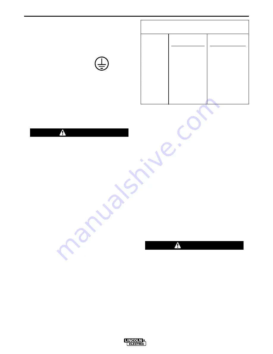
cle.  See Figure B.1.  The ground stud is marked with
the ground symbol.

If the RANGER 8+ DIESEL is connected to premises
wiring such as a home or shop, it must be properly
connected to the system earth ground. 

WELDING CABLE CONNECTIONS

CABLE SIZE AND LENGTH

Be sure to use welding cables that are large enough.
The correct size and length becomes especially
important when you are welding at a distance from the
welder.

Table A.1 lists recommended cable sizes and lengths
for rated current and duty cycle.  Length refers to the
distance from the welder to the work and back to the
welder.  Cable diameters are increased for long cable
lengths to reduce voltage drops.

Lincoln Electric offers a welding accessory kit with the
properly specified welding cables.  See the
ACCESSORIES section of this manual for more infor-
mation.

WARNING

Table A.1

CABLE INSTALLATION

Install the welding cables to your RANGER 8+
DIESEL as follows.  See Figure B.1 for location of
parts.

1. The diesel engine must be OFF to install welding

cables.

2. Remove the flanged nuts from the output terminals.

3. Connect the electrode holder and work cables to

the weld output terminals.  The terminals are identi-
fied on the case front.

4. Tighten the flanged nuts securely.

5. Be certain that the metal piece you are welding (the

“work”) is properly connected to the work clamp and
cable.

6. Check and tighten the connections periodically.

• Loose connections will cause the output terminals to

overheat.  The terminals may eventually melt.

• Do not cross the welding cables at the output termi-

nal connection. Keep the cables isolated and sepa-
rate from one another.

------------------------------------------------------------------------

CAUTION

TOTAL  COMBINED  LENGTH  OF

ELECTRODE  AND  WORK  CABLES

0-50 Ft.

50-100 Ft.

100-150 Ft.

150-200 Ft.

200-250 Ft.

250 Amps

40% Duty Cycle

3 AWG

3 AWG

2 AWG

1 AWG

1/0 AWG

250 Amps

100% Duty Cycle

1 AWG

1 AWG

1 AWG

1 AWG

1/0 AWG

Содержание RANGER 8 + DIESEL

Страница 1: ...ERATE OR REPAIR THIS EQUIPMENT WITHOUT READING THIS MANUAL AND THE SAFETY PRECAUTIONS CONTAINED THROUGHOUT And most importantly think before you act and be careful R RANGER 8 DIESEL For use with machines having Code Numbers 10533 Sales and Service through Subsidiaries and Distributors Worldwide Cleveland Ohio 44117 1199 U S A TEL 216 481 8100 FAX 216 486 1751 WEB SITE www lincolnelectric com World...

Страница 2: ...R WEARERS SHOULD CONSULT WITH THEIR DOCTOR BEFORE OPERATING Read and understand the following safety highlights For additional safety information it is strongly recommended that you purchase a copy of Safety in Welding Cutting ANSI Standard Z49 1 from the American Welding Society P O Box 351040 Miami Florida 33135 or CSA Standard W117 2 1974 A Free copy of Arc Welding Safety booklet E205 is availa...

Страница 3: ...rical earth ground 3 f Maintain the electrode holder work clamp welding cable and welding machine in good safe operating condition Replace damaged insulation 3 g Never dip the electrode in water for cooling 3 h Never simultaneously touch electrically hot parts of electrode holders connected to two welders because voltage between the two can be the total of the open circuit voltage of both welders ...

Страница 4: ...event the welding sparks from starting a fire Remember that welding sparks and hot materials from welding can easily go through small cracks and openings to adjacent areas Avoid welding near hydraulic lines Have a fire extinguisher readily available 6 b Where compressed gases are to be used at the job site special precautions should be used to prevent hazardous situations Refer to Safety in Weldin...

Страница 5: ...n inflammables 4 Des gouttes de laitier en fusion sont émises de l arc de soudage Se protéger avec des vêtements de protection libres de l huile tels que les gants en cuir chemise épaisse pan talons sans revers et chaussures montantes 5 Toujours porter des lunettes de sécurité dans la zone de soudage Utiliser des lunettes avec écrans lateraux dans les zones où l on pique le laitier 6 Eloigner les ...

Страница 6: ...quipment CAUTION Please Examine Carton and Equipment For Damage Immediately When this equipment is shipped title passes to the purchaser upon receipt by the carrier Consequently Claims for material damaged in shipment must be made by the purchaser against the transportation company at the time the shipment is received Please record your equipment identification information below for future referen...

Страница 7: ...ther Features B 1 Recommended Applications B 2 Limitations B 2 Additional Safety Precautions B 2 Controls and Settings B 3 Machine Controls B 3 Engine Operation B 5 Before Starting the Engine B 5 Starting the Engine B 5 Stoping the Engine B 5 Break In Period B 6 Welding Operation B 6 Welding Process B 7 Stick Constant Current Welding B 7 TIG Constant Current Welding B 7 Wire Feed Welding CV B 7 Su...

Страница 8: ...ne Maintenance D 1 Engine Adjustments D 2 Slip Rings D 2 Battery D 2 Engine Maintenance Components D 2 Troubleshooting Section E Safety Precautions E 1 How to Use Troubleshooting Guide E 1 Troubleshooting Guide E 2 Wiring Diagram Dimension Print Section F Parts List P314 Series ...

Страница 9: ... RATED OUTPUT WELDER HEIGHT WIDTH DEPTH WEIGHT 30 75 in 19 09 in 48 12 in 695 lbs 781 1 mm 484 9 mm 1222 2 mm 315 Kg OUTPUT GENERATOR Welding Output Volts at Rated Amps Duty Cycle Max OCV 3700 RPM DC Constant Current 225 amps 25 volts 100 AC Constant Current 250 amps 25 volts 100 80 volts RMS DC Constant Voltage 200 amps 20 volts 100 Auxiliary Power 1 9 000 Watts 60 Hz 80 Amps 115 Volts 40 Amps 23...

Страница 10: ... Keep away from moving parts See additional warning information at front of this operator s manual WARNING Always operate the RANGER 8 DIESEL with the case roof on and all machine components completely assembled This will protect you from the dangers of moving parts hot metal surfaces and live electrical devices STORING 1 Store the machine in a cool dry place when it is not in use Protect it from ...

Страница 11: ...the under carriage to insure stability side to side and front to back when being moved and when standing by itself while being operated or serviced WARNING 4 Typical conditions of use i e travel speed rough ness of surface on which the undercarriage will be operated environmental conditions likely mainte nance 5 Conformance with federal state and local laws 1 1 Consult applicable federal state and...

Страница 12: ...ATTERY ACID can burn eyes and skin Wear gloves and eye protection and be careful when working near battery Follow instructions printed on battery WARNING IMPORTANT To prevent ELECTRICAL DAMAGE WHEN a Installing new batteries b Using a booster Use correct polarity Negative Ground The RANGER 8 DIESEL is shipped with the negative battery cable disconnected Before you operate the machine attach the di...

Страница 13: ...comes especially important when you are welding at a distance from the welder Table A 1 lists recommended cable sizes and lengths for rated current and duty cycle Length refers to the distance from the welder to the work and back to the welder Cable diameters are increased for long cable lengths to reduce voltage drops Lincoln Electric offers a welding accessory kit with the properly specified wel...

Страница 14: ...se 40 ampere service Only a licensed certified trained electrician should install the machine to a premises or residential elec trical system Be certain that The installation complies with the National Electrical Code and all other applicable electrical codes The premises is isolated and no feedbacking into the utility system can occur Certain state and local laws require the premises to be isolat...

Страница 15: ...EUTRAL BUS GROUND PREMISES DISCONNECT AND SERVICE OVERCURRENT PROTECTION GND N NOTE No 8 COPPER CONDUCTOR CABLE SEE NATIONAL ELECTRICAL CODE FOR ALTERNATE WIRE SIZE RECOMMENDATIONS 230 VOLT GROUNDED CONDUCTOR 40AMP 230 VOLT DOUBLE POLE CIRCUIT BREAKER DOUBLE POLE DOUBLE THROW SWITCH RATING TO BE THE SAME AS OR GREATER THAN PREMISES SERVICE OVERCURRENT PROTECTION 50 AMP 115 230 VOLT PLUG NEMA TYPE ...

Страница 16: ...t Adjustment Use with a broad range of AC DC Electrodes Including Fleetweld 5P DC SEMIAUTOMATIC WIRE FEED WELDING Constant Voltage CV Tap Setting for 40 200 Amps 100 Duty Cycle Excellent Performance with 068 1 7mm NR 211 MP Innershield Electrode Limited MIG Welding with L 50 L 56 using blended Argon Shielding Gas The Recommended Wire Feeder is the LN 25 but Can Also be Used with the LN 7 Wire Feed...

Страница 17: ...that are normally per formed using stick welding SMAW TIG welding GTAW MIG GMAW welding and Innershield FCAW welding The RANGER 8 DIESEL is not recommended for pipe thawing During welding generator power is limited and out put voltages can drop Therefore DO NOT OPER ATE ANY SENSITIVE ELECTRICAL EQUIPMENT WHILE YOU ARE WELDING See Table B 4 for permissible simultaneous welding and auxiliary power l...

Страница 18: ... PUSH BUTTON When the push button is held the starter motor cranks over the engine release the Button once the engine starts NOTE If you press the START push button when the engine is running you may damage the ring gear or starter motor 6 OIL PRESSURE GAUGE Indicates the amount of oil pressure present when the engine is running 7 BATTERY LIGHT Is off when battery charging system is functioning no...

Страница 19: ...pplying 230 volt power to operate one electrical device 14 15 AMP 115 VOLT DUPLEX RECEPTACLES Connection point for supplying 115 volt power to operate one or two electrical devices 15 CIRCUIT BREAKERS Open the receptacle outlets if a fault is detected in the circuit 16 GLOW PLUG PUSH BUTTON Activates glow plug to preheat engine for cold weath er starting 17 FUEL LEVEL GAUGE Displays the level of d...

Страница 20: ...hten securely WARNING WARNING USE DIESEL FUEL ONLY Purchase diesel fuel in quantities that will be used within 30 days to assure freshness STARTING THE ENGINE Remove all loads connected to the AC power recepta cles and the welder before starting the diesel engine 1 Check for proper oil level on the oil dipstick 2 Set IDLER switch to AUTO 3 Check the fuel gauge to make sure that there is an adequat...

Страница 21: ... 1 0 gallons hour 3 9 liters hour 0 8 gallons hour 3 2 liters hour WELDING OPERATION The RANGER 8 DIESEL machines can deliver from 40 to 250 amps of constant current for AC stick weld ing and 40 to 225 amps of constant current DC stick welding The RANGER 8 DIESEL can deliver 40 to 200 amps of constant voltage current for DC semiau tomatic wire feed welding AC DC constant current TIG welding is pos...

Страница 22: ...ield electrode recommended for use with the RANGER 8 DIESEL is NR 211 MP The electrode sizes and welding ranges that can be used with the RANGER 8 DIESEL are shown in the follow ing table SETTINGS FOR PURE TUNGSTEN TUNGSTEN RANGE SWITCH APPROXIMATE DIAMETER in SETTINGS CURRENT RANGE 1 8 70 90 or 125 80 150 Amps 3 32 50 70 or 90 45 130 Amps 1 16 50 or 70 40 80 Amps SETTINGS FOR 1 THORIATED TUNGSTEN...

Страница 23: ...o high idle TIG K930 2 K938 1 Yes HIGH Cold Press Amptrol contactor K936 K892 1 closes welding WITH AMPTROL starts immediately WIRE FEED LN 25 WITH No AUTO Cold Press gun trigger LN 25 INTERNAL CONTACTOR contactor closes Welding starts immediately and engine goes to high idle NOTE Output Control must be set above 3 WIRE FEED LN 7 WITH Yes HIGH Cold Press gun trigger K240 CONTACTOR KIT contactor cl...

Страница 24: ...ated is not exceeded This may necessitate 230 volt oper ation only SIMULTANEOUS WELDING AND POWER LOADS Auxiliary power ratings are with no welding load Simultaneous welding and power loads are permitted by the following table The permissible currents shown assume that current is being drawn from either the 115 volt or 230 volt supply not both at the same time Output Selector Setting Welding Outpu...

Страница 25: ...n both legs of the three wire cir cuit as shown below FIGURE B 3 115V DUPLEX RECEPTACLES The 115V auxiliary power receptacles should only be used with three wire grounding type plugs or approved double insulated tools with two wire plugs Maximum Current Draw from 115V Duplex Receptacles No Welding EACH HALF OF EACH 115V DUPLEX TOTAL FROM ONE 115V DUPLEX TOTAL FROM BOTH 115V DUPLEXES LOAD FROM 115 ...

Страница 26: ...t to be mounted in machine TIG WELDING OPTIONS ACCESSORIES K930 2 TIG Module Provides high frequency and shielding gas control for AC and DC GTAW TIG welding applications Its compact case is designed for easy carrying complete with a handle High frequen cy bypass is built in The K938 1 Contactor Kit must be field installed in the TIG Module when used with a RANGER 8 DIESEL Additionally the K936 3 ...

Страница 27: ...ol cable Provides cold electrode until gun trigger is pressed Includes gas solenoid Remote control Receptacle Kit K892 1 and Remote voltage Control Kit K444 1 are required for voltage control at the feeder LN 7 Contactor Kit K240 is required Magnum Gun is required for gas shielded welding Innershield Gun is required for gasless welding RANGER 8 DIESEL ...

Страница 28: ...for the installa tion An S16586 length remote voltage sensing work lead S17742 10 2 92 may be ordered for this purpose Connect it directly to the work piece independent of the welding work cable For conve nience this extended 21 lead should be taped to the welding work lead N G Tape up bolted connection where lead 21 is extended N H Idler switch on power source must be in high idle position N J If...

Страница 29: ...tenance section of the Engine Owner s Manual for the maintenance schedule and fuel filter replacement 5 Blow out the machine with low pressure air periodically In particularly dirty locations this may be required once a week RANGER 8 DIESEL SAFETY PRECAUTIONS Have qualified personnel do maintenance and troubleshooting work Turn the engine off before working inside the machine Remove guards only wh...

Страница 30: ...ging from an external charger disconnect the negative battery cable first and then the positive battery cable before attaching the charger leads Failure to do so can result in damage to the internal charger components When reconnecting the cables connect the positive cable first and the negative cable last Hardware Both English and Metric fasteners are used in this welder ENGINE MAINTENANCE COMPON...

Страница 31: ... you do not understand or are unable to perform the Recommended Course of Action safely contact you local Lincoln Authorized Field Service Facility HOW TO USE TROUBLESHOOTING GUIDE Service and Repair should only be performed by Lincoln Electric Factory Trained Personnel Unauthorized repairs performed on this equipment may result in danger to the technician and machine operator and will invalidate ...

Страница 32: ... Faulty rotor 4 Faulty Potentiometer R1 5 Faulty stator Field winding 6 Faulty Field rectifier D2 7 Faulty P C Board 1 Idler switch on High Idle 2 External load on welder or auxiliary power 3 Faulty idler solenoid 4 Faulty P C Board 1 Refer to wiring diagram check related leads 2 Refer to wiring diagram and check all related leads 200 224 200A 200B 201 201A 3 Lift brushes and check rotor resistanc...

Страница 33: ...iliary power load less than 100 to 150 watts 3 Faulty P C Board 4 Insufficient voltage present between terminals 253 and 5G Volatge should be 12 V DC 5 Faulty wiring in solenoid circuit 1 Battery will not hold a charge Faulty Battery 2 No or insufficient charging current 3 Loose battery cable connection s 1 Out of fuel 1 Make certain work clamp is tightly connected to clean base metal 2 Check for ...

Страница 34: ...es or are unable to perform the tests repairs safely contact your Local Lincoln Authorized Field Service Facility for technical troubleshooting assistance before you proceed CAUTION PROBLEMS SYMPTOMS POSSIBLE AREAS OF MISADJUSTMENTS S RECOMMENDED COURSE OF ACTION G Engine does not develop full power 1 Fuel filter clogged 2 Air filter clogged 1 Replace 2 Clean ...

Страница 35: ...m is for reference only It may not be accurate for all machines covered by this manual The specific diagram for a particular code is pasted inside the machine on one of the enclosure panels If the diagram is illegible write to the Service Department for a replacement Give the equipment code number ...

Страница 36: ...F 2 DIAGRAMS F 2 RANGER 8 DIESEL M19108 12 11 97 MAXIMUM OVERALL DIMENSIONS LENGTH 48 12 IN WIDTH 19 09 IN HEIGHT 30 75 IN ...

Страница 37: ...NOTES RANGER 8 ...

Страница 38: ...lletin ED 80 or call 216 383 2259 and ask for the Welding School Registrar Lincoln Welding School BASIC COURSE 700 00 5 weeks of fundamentals There is a 10 discount on all orders of 50 00 or more for shipment at one time to one location Orders of 50 or less before discount or orders outside of North America must be prepaid with charge check or money order in U S Funds Only Prices include shipment ...

Страница 39: ...electrically live parts or electrode with skin or wet clothing Insulate yourself from work and ground No toque las partes o los electrodos bajo carga con la piel o ropa moja da Aislese del trabajo y de la tierra Ne laissez ni la peau ni des vête ments mouillés entrer en contact avec des pièces sous tension Isolez vous du travail et de la terre Berühren Sie keine stromführenden Teile oder Elektrode...

Страница 40: ...gute Be und Entlüftung des Arbeitsplatzes Mantenha seu rosto da fumaça Use ventilação e exhaustão para remover fumo da zona respiratória Turn power off before servicing Desconectar el cable de ali mentación de poder de la máquina antes de iniciar cualquier servicio Débranchez le courant avant l entre tien Strom vor Wartungsarbeiten abschalten Netzstrom völlig öff nen Maschine anhalten Não opere co...

Отзывы: