IM3102
10/2019
REV03
POWERTEC i380C & i450C ADVANCED
OPERATOR’S MANUAL
ENGLISH
Lincoln Electric Bester Sp. z o.o.
ul. Jana III Sobieskiego 19A, 58-263 Bielawa, Poland
www.lincolnelectric.eu
Страница 1: ...IM3102 10 2019 REV03 POWERTEC i380C i450C ADVANCED OPERATOR S MANUAL ENGLISH Lincoln Electric Bester Sp z o o ul Jana III Sobieskiego 19A 58 263 Bielawa Poland www lincolnelectric eu...
Страница 2: ...ference record in the table below your equipment identification information Model Name Code Serial Number can be found on the machine rating plate Model Name Code Serial number Date Where Purchased EN...
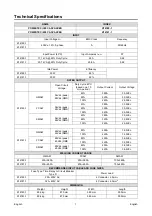
Страница 3: ...Vdc 100 240A 26 0Vdc FCAW 54Vdc peak 48Vdc RMS 40 380A 33 0Vdc 60 320A 30 0Vdc 100 240A 26 0Vdc SMAW 54Vdc peak 48Vdc RMS 40 380A 35 2Vdc 60 320A 32 8Vdc 100 240A 29 6Vdc K14181 1 GMAW 60Vdc peak 49Vd...
Страница 4: ...22 m min 4 37 Solid Wires Aluminum Wires Cored Wires K14180 1 0 8 1 4 mm 1 0 1 2 mm 0 9 1 2 mm K14181 1 0 8 1 6m 1 0 1 6 mm 0 9 1 6 mm Protection Rating Maximum Gas Pressure Operating Humidity t 20 C...
Страница 5: ...system impedance complies with the impedance restrictions Consider the following guidelines to reduce electromagnetic emissions from the machine Connect the machine to the input supply according to t...
Страница 6: ...AGNETIC FIELDS MAY BE DANGEROUS Electric current flowing through any conductor creates electric and magnetic fields EMF EMF fields may interfere with some pacemakers and welders having a pacemaker sha...
Страница 7: ...d away from areas where they may be subjected to physical damage or the welding process including sparks and heat sources MOVING PARTS ARE DANGEROUS There are moving mechanical parts in this machine w...
Страница 8: ...not operate in areas with an ambient temperature greater than 40 C Duty cycle and Overheating The duty cycle of a welding machine is the percentage of time in a 10 minute cycle at which the welder ca...
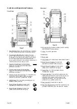
Страница 9: ...cket For connecting a welding gun for GMAW FCAW process 7 Quick Connect Coupling Coolant outlet supplies cool coolant to the torch gun 8 Quick Connect Coupling Coolant inlet takes warm coolant from to...
Страница 10: ...he machine does not include a spooled wire 24 Fuse F1 Use the 2A 400V 6 3x32mm low blow fuse 25 Wire drive feeding system 4 Roll wire drive mechanisms with quick change feed rolls 26 Terminal Block of...
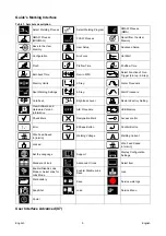
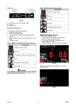
Страница 11: ...ot Welding Settings 4 Step Start Procedure Cold Feed Brightness Level Restore Factory Setting View Software and Hardware Version Information A B Procedure USB Memory Check Mark Resignation Mark Access...
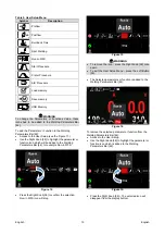
Страница 12: ...ight Knob 36 Use the Right Knob 36 to highlight the Configuration icon Press the Right Knob 36 to confirm decision Use the Right Knob 36 to highlight UI look icon Press the Right Knob 36 to confirm de...
Страница 13: ...ion of the gun s trigger change Pinch Configuration Menu Setup User Setup WARNING The availability parameters depend on the selected welding program welding process Table 4 SMAW Welding Parameters Bar...
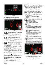
Страница 14: ...Welding Parameters Bar Use the Right Knob 36 to highlight the icon Support Press the Right Knob 36 to confirm the selection The Support Menu enables to get knowledge of the following points Accessorie...
Страница 15: ...n icon which will be added to the Welding Parameters Bar 44 for example Run in WFS Figure 12 Press the Right Knob 36 to confirm the selection Run in WFS icon will drop Figure 13 WARNING To remove the...
Страница 16: ...he machine will ramp up or down from the Start Procedure to the preset Welding Procedure Adjust time range from 0 seconds OFF to 10 seconds Crater Procedure controls the WFS or value in ampere units a...
Страница 17: ...Save the following data can be save on a USB Memory Stick Table 7 Save and restore selection Symbol Description Current Welding Settings Advanced Parameters Configuration P menu M All welding program...
Страница 18: ...USB Menu press the Left Button 37 or disconnect the USB Memory Stick from the USB receptacle Load restore the data from the USB Device to the machine memory To load the data from USB Memory Connect t...
Страница 19: ...cess the Settings and Configuration Menu Press the Button 37 or Right Knob 36 to get access of Welding Parameters Bar Use the Right Knob 36 to highlight the icon Configuration Press the Right Knob 36...
Страница 20: ...r which will be changed Press the Right Knob 36 to confirm Use the Right Knob 36 to change the value Press the Right Knob 36 to confirm Figure 37 shows the effect of changing the values of parameters...
Страница 21: ...Knob 36 The password setting menu is shown on the display Figure 42 Turn Right Knob 36 to select numbers 0 9 Press Right Knob 36 to confirm first character of the password Next numbers are selected in...
Страница 22: ...isable Jobs menu is shown on the display Figure 47 Use the Right Knob 36 to highlight the job number The icon of chosen job will disappear from the lower part of the display Figure 48 Note The jobs wh...
Страница 23: ...ameters Bar Also the Load Memory and Save Memory options will be blocked in this mode Set the Language user can choose interface language English Polish Finnish French German Spanish Italian Dutch Rom...
Страница 24: ...of the device To set the configuration parameters Access to the Settings and Configuration Menu Use the Right Knob 36 to highlight the configuration menu icon Figure 58 Press the Right Knob 36 The Co...
Страница 25: ...settings The procedure can be changed as many times as needed during the weld Release the trigger to stop welding When the next weld is made the system will start again with procedure A IntegralTrigP...
Страница 26: ...ol connections operate Joystick MIG Gun European default Use this setting while MIG welding with a push MIG gun with a joystick control Stick TIG and gouge welding currents are set at the User Interfa...
Страница 27: ...Display Workpoint as Amps Option Determines how workpoint is displayed No factory default The workpoint is displayed in the format defined in the weld set Yes All workpoint values are displayed as an...
Страница 28: ...access to special service functions WARNING Service Menu is available when USB storage device is connected Figure 62 Table 14 Service Menu Symbol Description Service weld logs Weld History SnapShot Se...
Страница 29: ...36 to start Snapshot process Figure 67 Welding GMAW and FCAW Process in non synergic mode During non synergic mode wire feed speed and welding voltage are independent parameters and must be set by the...
Страница 30: ...Process POWERTEC i380C ADVANCED POWERTEC i450C ADVANCED does not include the electrode holder with lead necessary for SMAW welding but the one can be purchased separately Procedure of begin welding of...
Страница 31: ...f Depending on welding process connect the proper gun to the euro socket the rated parameters of the gun and of the welding machine should be matched Remote the nozzle from the gun and contact tip or...
Страница 32: ...but at least once a year Perform the routine maintenance and in addition Keep the machine clean Using a dry and low pressure airflow remove the dust from the external case and from the cabinet inside...
Страница 33: ...r is not listed Contact the Lincoln Electric Service Department for any code number not listed Use the illustration of assembly page and the table below to determine where the part is located for your...
Страница 34: ...I37 4PCS BLUE RED KP14150 V10 12 ROLL KIT 1 0 1 2VT FI37 4PCS RED ORANGE KP14150 V12 16 ROLL KIT 1 2 1 6VT FI37 4PCS ORANGE YELL KP14150 V16 24 ROLL KIT 1 6 2 4VT FI37 4PCS YELL GREY KP14150 V09 11 RO...