English
English
43
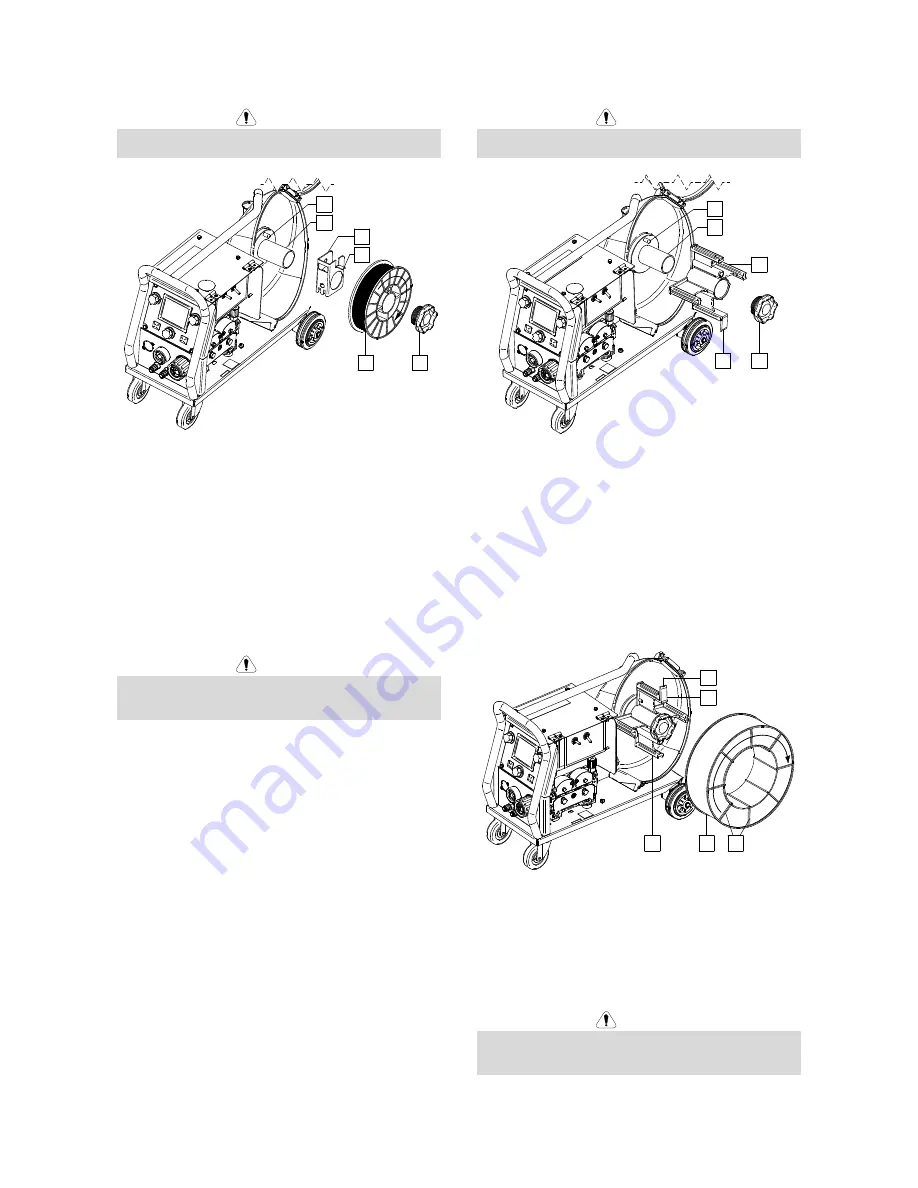
Wire Spool Type S200 Loading
WARNING
Turn the input power OFF at the welding power source
before installation or changing a wire spool.
28
30
31
32
33
34
Figure 93
••••
Turn the input power OFF.
••••
Open the spool wire case.
••••
Unscrew the Locking Nut [28] and remove it from the
Spindle [30].
••••
Place the adapter of spool type S200 [32] on the
spindle [30] making certain the spindle brake pin [31]
is put in the hole in back side of the adapter [32]. The
adapter of spool type S200 can be purchased
separately (see "Accessories" chapter).
••••
Place the spool type S200 [34] on the spindle [30]
making certain that the adapter brake pin [33] is put
in the hole in the back side of the spool.
WARNING
Position the spool type S200 so that it will rotate in a
direction when feeding so as to be de-reeled from
bottom of the spool.
••••
Re-install the locking nut [28]. Make sure that the
locking nut is tightened.
Wire Spool Type B300 Loading
WARNING
Turn the input power OFF at the welding power source
before installation or changing a wire spool.
28
30
31
36
35
Figure 94
••••
Turn the input power OFF.
••••
Open the spool wire case.
••••
Unscrew the Locking Nut [28] and remove it from the
Spindle [30].
••••
Place the adapter of spool type B300 [35] on the
spindle [30]. Make certain that the spindle brake pin
[31] is put in the hole in the back side of the adapter
[35]. The adapter of spool type B300 can be
purchased separately (see "Accessories" chapter).
••••
Re-install the locking nut [28]. Make sure that the
locking nut is tightened.
35
36
37
38
39
Figure 95
••••
Rotate the spindle and adapter so the retaining
spring [36] is at the 12 o'clock position.
••••
Place the spool type B300 [38] on the adapter [35].
Set one of the B300 inside cage wires [39] on the
slot [37] in the retaining spring tab [36] and slide the
spool onto the adapter.
WARNING
Position the spool type B300 so that it will rotate in a
direction when feeding so as to be de-reeled from
bottom of the spool.


