5
MAINTENANCE
5
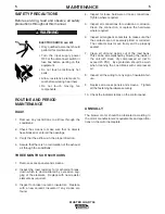
SAFETY PRECAUTIONS
Before servicing, read and observe all safety
precautions throughout this manual.
ELECTRIC SHOCK can kill.
• Only qualified personnel should
perform this maintenance.
• Turn the input supply power
OFF at the disconnect switch or
fuse box before working on this
equipment.
• Do not touch electrically hot
parts.
• Allow resistance elements to
cool before working near them.
• Do not touch moving fan
components.
------------------------------------------------------------------------
ROUTINE AND PERIOD
MAINTENANCE
DAILY
1.
Remove any restrictions to airflow through the
Load Bank.
2. Check the screens to make sure that no objects
have blocked or entered the openings.
3.
Verify that the airflow is in the proper direction.
4.
Assure that there is no recirculation of the exhaust
air through the Load Bank.
THREE MONTHS OR 500 HOURS
1.
Remove access panels and screens.
2.
Inspect the load resistors for mechanical break-
down which is demonstrated by excessive sag-
ging of the elements.
Replace with new resistor
elements as required.
3.
Inspect for broken ceramic insulators.
Replace
with a new ceramic insulator if any cracks are
found.
4.
Inspect for loose hardware or loose connections.
Tighten where required.
5.
Inspect all connections for oxidation or corrosion.
Clean the connection or replace the hardware
where required.
6.
Inspect all magnetic contactors to make sure that
the contacts are not severely pitted or corroded.
The contacts must move freely and be properly
seated.
7.
Clean all dirt and debris out of the load bank.
This can be accomplished by blowing the inside of
the unit with clean, dry compressed air (not to
exceed 40 PSI).
Eye protection should be worn
when cleaning the Load Bank with compressed
air.
8.
Inspect all the wiring for any sign of insulation fail-
ure.
9.
Replace all access panels and screens.
Tighten
all the fastening hardware securely.
10. Check the indicator lamps on the control panel.
ANNUALLY
The blower motor should be lubricated according to
the motor manufacturers' requirements and specifica-
tions on the motor nameplate.
MASTER LOAD 750
WARNING
Содержание MASTER LOAD 750
Страница 18: ...10 DIAGRAMS 10 MASTER LOAD 750 D26300 3 5 97 MASTERLOAD 750 WIRING DIAGRAM ...
Страница 19: ...11 DIAGRAMS MASTER LOAD 750 11 SB2561 2 22 96 MASTERLOAD 750 DIMENSION PRINT ...
Страница 20: ...PARTS MASTER LOAD 750 D26244 SHT 1 2 3 6 97 MASTERLOAD 750 GENERAL ASSEMBLY ...
Страница 23: ...NOTES ...
Страница 24: ...NOTES ...
Страница 25: ...NOTES ...


