GENERAL DESCRIPTION
The Master Load 750 Load Bank is designed for elec-
trically loading and testing power sources. The unit is
designed for production line and job site use.
The total loading capability of the Master Load 750 is
in fixed steps of 25, 25, 50, 50, 100, 250, 250 Amps
@ 50V AC or DC, totaling 750 Amps. Using the tog-
gle switches on the control panel, any combination of
the available load steps may be selected to achieve a
desired load.
CONTROL UNIT
The loads described above are controlled from an
integral control panel.
1.
CONTROL POWER ON/OFF switch - Applies
power to the load bank and starts the blower.
The CONTROL POWER indicator lights when
power is applied.
2.
BLOWER FAIL indicator - Indicates an air fail-
ure condition or insufficient cooling airflow.
3.
MASTER LOAD ON/OFF switch - Allows
instantaneous connection and disconnection
2
DESCRIPTION
MASTER LOAD 750
2
of all switched ON load steps.
4.
LOAD STEPS switches - Connect and discon-
nect load steps. Values are shown above
each switch.
5.
Analog Meters - Monitors DC volts, DC amps,
AC volts, and AC amps applied to the load
bank.
ENCLOSURE
The outside dimensions of the Master Load 750 Load
Bank are listed on Technical Specifications page at
the beginning of this section of the manual. The Load
Bank is mounted on casters. One set of casters has
lockable wheels.
Do not allow the Load Bank to be placed where hot
exhaust air can recirculate back through the unit caus-
ing a constant rise in cooling air temperature.
------------------------------------------------------------------------
The Master Load 750 Load Bank contains a blower
(approximately 82dBA at 3 ft.) which provides the nec-
essary cooling air for the load elements. An exhaust
temperature sensor is provided to monitor the exhaust
temperature.
This switch is electrically interlocked
with the load application circuit. If an unsafe tempera-
ture is detected in the exhaust of the Load Bank, the
BLOWER FAIL light comes on and the load is discon-
nected from the resistive elements.
Air to cool the load elements enters the screened
intakes located on one end of the Load Bank. The air
passes over the resistive elements and is then dis-
charged through the screened opening at the other
end of the Load Bank.
The Load Bank also contains fuses for short circuit
protection. The control circuit is protected with a 15
amp fuse while the voltmeters are protected with 3
amp fuses.
Do not operate the Load Bank with any screen or
cover removed.
This may expose the operator to
high voltage and rotating fan blades.
---------------------------------------------------------------------
Do not exceed the voltage rating of load resistive cir-
cuit configuration.
------------------------------------------------------------------------
CAUTION
WARNING
CAUTION
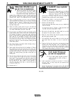
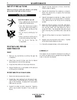
SAFETY PRECAUTIONS
Before installation, read and observe all safe-
ty precautions throughout this manual.
ELECTRIC SHOCK can kill.
• Turn the input supply power
OFF at the disconnect switch or
fuse box before working on this
equipment.
• Do not touch electrically hot
parts.
HOT EXHAUST can burn skin.
• Allow resistance elements to cool
before working near them.
ROTATING FAN can cause injury.
• Do not touch moving fan
components.
------------------------------------------------------------------------
WARNING
Содержание MASTER LOAD 750
Страница 18: ...10 DIAGRAMS 10 MASTER LOAD 750 D26300 3 5 97 MASTERLOAD 750 WIRING DIAGRAM ...
Страница 19: ...11 DIAGRAMS MASTER LOAD 750 11 SB2561 2 22 96 MASTERLOAD 750 DIMENSION PRINT ...
Страница 20: ...PARTS MASTER LOAD 750 D26244 SHT 1 2 3 6 97 MASTERLOAD 750 GENERAL ASSEMBLY ...
Страница 23: ...NOTES ...
Страница 24: ...NOTES ...
Страница 25: ...NOTES ...


