


Section 6 - Setting Up for Welding
The following items are required:
1. REDI-MIG Remote or other suitable constant voltage
power source.
2. A reel of wire of suitable size and type.
3. A control/power cable assembly to connect the wire
feeder to the power source.
4. A suitable gun and cable assembly with a “Euro”
connector and the correct contact tip and, if necessary,
gas nozzle for the consumable being used. See
“Connections” on Page 8 for details of recommended
REDI-MIG guns for use with REDI-MIG Remote power
sources.
5. Correct drive rolls for the wire size and type to be used.
The wire feeder is supplied with a 0.9/1.2mm solid wire
feed roll as standard; drive rolls for other types and sizes
are available as spare parts.
6. A work return cable and clamp.
7. Normal welding accessories including helmet or hand
shield with suitable lens, gloves etc.
8. If a gas shielded process is to be used; appropriate gas
cylinder, regulator/flowmeter and hose.
Connect the control and welding cables to the welding
power source.
If gas shielding is required, connect the gas hose.
Remember that gas cylinders may explode if damaged, so
ensure that all gas cylinders are securely mounted.
Ensure that the correct type and size wire feed rolls are
fitted.
When replacing wire feed rolls, ensure that the key and
keyway are correctly positioned and tighten the knurled
locking screw securely.
Fit the spool of wire on to the 50mm spool hub so that as
wire is drawn from the spool, the spool turns clockwise
when looking at the spool. Carefully release the end of the
wire from the spool ensuring that the released end is held
to stop the wire from unravelling. Cut off the end kink to give
a smooth straight end of wire.
Obtain a gap between the wire feed roll and the pressure
roll by opening the cam latch. Feed the wire end into the
guide tube, between the drive rolls, and into the “Euro”
connector guide until it protrudes about 20mm out of the
front of the “Euro” connector. Close the drive rolls by
securing the cam latch. Ensure the rolls firmly hold the wire.
Fit the gun and cable assembly into the “Euro” connector by
slipping the end of wire into the cable wire hole. Tighten the
“Euro” connector lock ring.
Activate the power source, set the wire feed speed to
approximately one quarter turn and momentarily press the
gas purge/wire inch toggle switch downwards. The wire
feed roll should have turned, feeding the wire further up the
gun and cable assembly. Adjust the tension so that wire
feed smoothly.
Do not overtighten
.
Ensure there are no kinks or sharp bends in the gun cable
and press the wire inch toggle switch downwards until the
wire emerges from the gun. It is good practice to remove
the tip when first feeding a new coil of wire, then refit the tip
over the wire and tighten. Cut off the end of the wire leaving
10mm to 15mm stick-out from the tip.
The wire feeder is now ready to weld.
Section 7 - Welding
Put in 2 Step trigger mode. Before beginning to weld,
ensure the wire protrudes from the gun tip by approximately
10-15mm. Ensure welding shield and other protective
clothing are in place. Present the protruding electrode just
off the work. Maintain a steady grip on the gun, protect your
eyes with a welding mask, then press and hold the gun
trigger to create the arc.
Adjust the wire feed speed and power source output to suit
the job. At the completion of the weld, release the gun
trigger and pull the gun away from the work to stop the arc.
4 Step trigger mode should only be used for long welds with
an experienced operator.
7.1 Changing Electrode Size and Type
When changing the electrode size or type, ensure the wire
feed drive roll is the correct size and type for the electrode.
Wire feed drive rolls have two grooves each of different
sizes.
Ensure the roll is located by the key and key way and firmly
secured by knurled screw.
When changing to aluminium welding a new drive roll,
cable liner and contact tip should be used.
All required equipment for aluminium welding is supplied in
the optional 1.2mm Aluminium Feeding Kit (KA1440-1 for
use with REDI-MIG 2 Guns or KA1440-4 for use with REDI-
MIG 240 Guns).
When changing to cored wire welding a new drive roll
should be used.
All required equipment for cored wire welding is supplied in
the optional 1.2mm Flux Cored Feeding Kit (KA1441-1 for
use with REDI-MIG 2 Guns or KA1441-4 for use with REDI-
MIG 240 Guns).
Also check electrode polarity, as different processes require
different polarity.
Ensure the correct gun liner and contact tip are used for
different wire sizes and processes.
7.2 Gun Tip
The gun tip should be replaced when worn. Replace with
the correct type and size for the wire type and diameter. Too
large a tip for the electrode wire will cause arcing within the
gun cable and possible jamming of the wire within the
cable. Gun tips screw in and out.
7.3 Adjusting Spool Tension
The spool should stop rotating when the wire feed roll
stops. Overrun of the spool can cause the coil of wire to
unravel. The spool hub should be tensioned so that it
neither drags nor overruns. The tension can be set by
adjusting the large nut inside the hub with a tube spanner.
IMA 600A
REDI-MIG 4D
Page 9
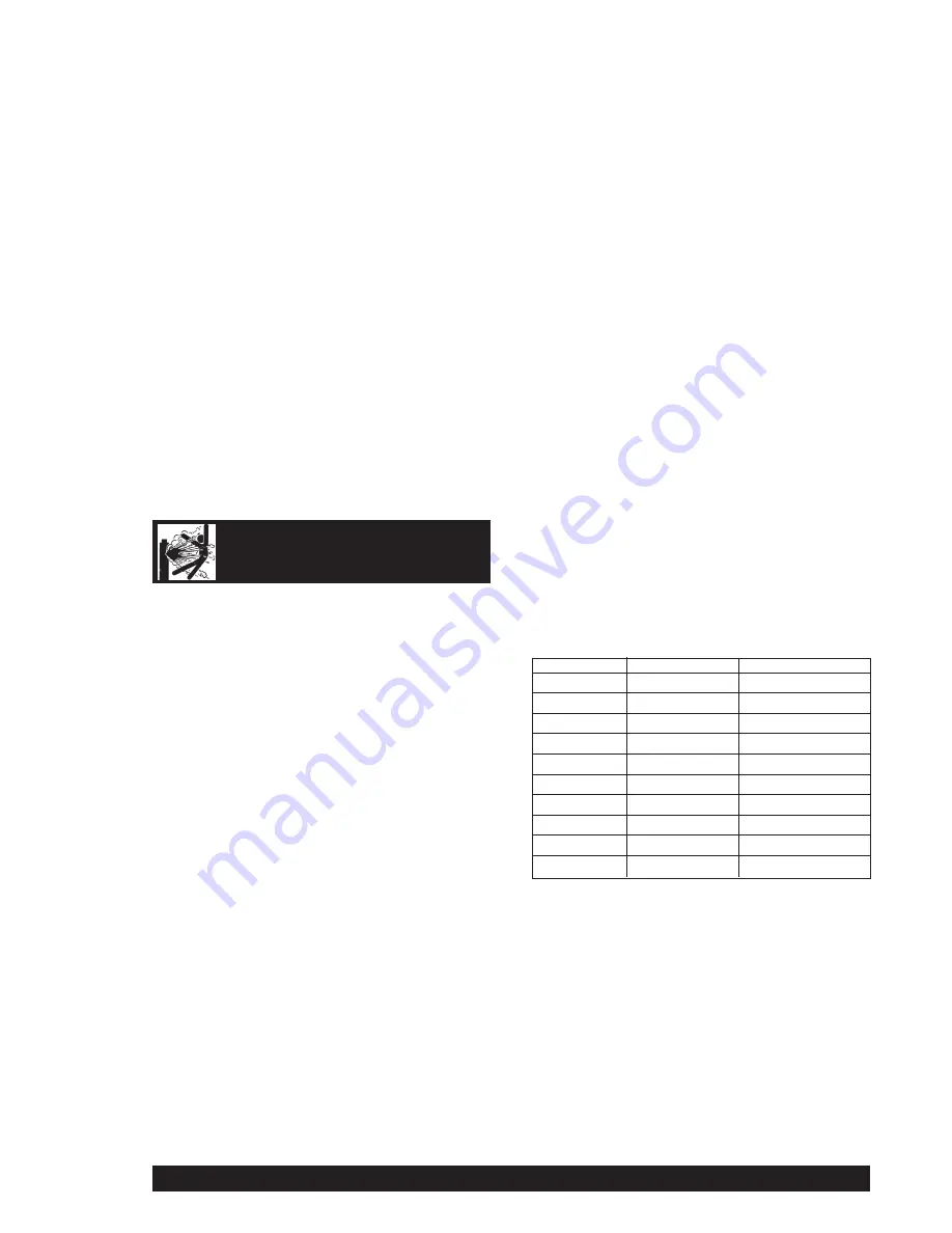
CYLINDER may explode
if damaged
Part No.
Size (mm)
Use with
AS4449-9
0.6 - 0.8
Solid Wire
AS4449-11
0.8 - 0.9
Solid Wire
AS4449-8
0.9 - 1.2
Solid Wire*
AS4449-2
1.0 - 1.2
Solid Wire
AS4449-5
0.8 - 1.0
Aluminium Wire
AS4449-12
0.9 - 1.2
Aluminium Wire
AS4449-6
1.2 - 1.6
Aluminium Wire
AS4449-3
0.8 - 1.0
Cored Wire
AS4449-13
0.9 - 12
Cored Wire
AS4449-4
1.2 - 1.6
Cored Wire
Available Drive Rolls
*
Standard on REDI-MIG Integrated and Remote machines
Содержание KA 1435
Страница 14: ...Page 14 REDI MIG 4D Remote IMA 600A NOTES...
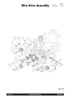
Страница 18: ...Page 18 REDI MIG 4D Remote IMA 600A Wire Drive Assembly AP 56 E Operative Apr 2004 Supersedes NEW Ref 410...
Страница 20: ...Page 20 REDI MIG 4D Remote IMA 600A Wire Drive Assembly AP 56 F Operative Apr 2004 Supersedes NEW Ref 410 2...
Страница 22: ...Page 22 REDI MIG 4D Remote IMA 600A NOTES...
Страница 23: ...IMA 600 REDI MIG 4D Remote Page 23 NOTES...


