

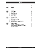
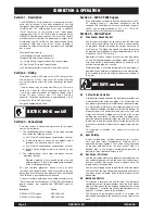


Section 1 - Description
The REDI-MIG 4D Wire Feeder has a drive plate with four
drive rolls (all driven). It has been designed for use with
continuous electrodes with or without an externally applied
shielding gas. The welding gun must have a standard
“Euro” connector at the machine end. Input power
requirements are 42V AC 50Hz, which is supplied by the
REDI-MIG Remote power source. The units also feature
electrical contacts to allow the power source output to be
switched on and off, so that the gun and electrode will be
electrically “cold” when not in use. A gas solenoid is
provided to automatically control gas flow when shielding
gas is used.
Front panel controls are:
(a) Electrode wire feed speed control
(b) Spot weld time switch and control
(c) “2 Step/4 Step” trigger mode switch for gun trigger
(d) “Gas Purge”/”Wire Inch” toggle switch
(e) A burnback control is situated in the wire bay area
Section 2 - Rating
Wire feeder rating is 400 amps max. at 60% duty cycle or
300 amps max. at 100% duty cycle. The current and duty
cycle must also be within the rated capacity of the power
source.
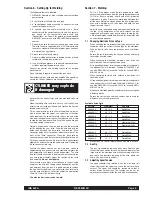
The wire feeder may be used with 0.6mm to 1.2mm dia.
solid wire, 1.0mm to 1.6mm aluminium wire and up to
1.6mm flux cored electrodes on standard spools (with a
50mm I.D. boss, 300mm max. O.D. and 15kg max.
capacity). Wire feed speed range is approximately 1 to 20
metres/min. (40 to 790 inch/mind.)
Weight is approximately 27kg.
Section 3 - Connections
The wire feeder is connected electrically to the power
source by two cables.
1. The control/power cable includes a 4-pin amphenol plug
and carries the following circuits:
a) 42V, 50Hz AC control power (isolated from chassis)
b) A closing contact to switch on the welders output
(provides 42V switched on pins ‘a’ and ‘b’)
c) 42V, 50Hz AC control power (isolated from chassis)
d) Earth. Chassis of power source to chassis of wire
feeder
2. The welding power cable from the power source’s
“electrode”* output.
*
Electrode polarity is determined by the wire and
welding process. Refer to the appropriate handbook
or the electrode packaging.
For gas shielded processes, connect the gas hose
(included with standard input cable assembly) to the gas
bottle regulator. Incoming gas pressure must not exceed
1000kPa and a gas regulator must be used.
Connect a suitable welding gun and cable assembly to the
“Euro” connector on the front panel. The REDI-MIG Remote
power sources are supplied with REDI-MIG guns as
follows:
Machine
Torch
REDI-MIG 255 Remote
REDI-MIG 240
REDI-MIG 325 Remote
REDI-MIG 360
Section 4 - 42V AC 50Hz Supply
If the welding power source to be used does not have a 42V
AC auxiliary supply, a step-down transformer will be
required. This transformer must have a minimum rating of
220VA and an output voltage of 42V + 5% 50Hz AC.
Contact Lincoln for further details required.
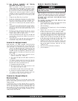
Section 5 - Control Panel
5.1 Wire Feeder Speed Control
Use this control to adjust the speed at which the electrode
wire feeds when welding. This is in effect a current control
as the power source will deliver the current necessary to
melt the wire. The higher the speed, the more current will
be required. Wire feed speed range is approximately 1 to 20
metres/min. (40 to 790 inch min.)
Operation of the gun trigger, switches the wire feed motor
on and off, depending upon the trigger mode setting. The
wire feed motor is dynamically braked to minimise wire
overrun after welding has ceased.
Welding voltage is available immediately the gun trigger is
operated. When welding is stopped there is a delay to allow
the electrode to burn back slightly and prevent sticking in
the crater.
5.2 2 Step/4 Step Operation
A two position toggle switch on the front panel provides two
modes of operation of the gun trigger. In 2 Step mode, the
gun trigger is pressed to start welding and released to stop.
In 4 Step mode, pressing the gun trigger only operates the
gas solenoid, allowing shielding gas to flow. Releasing the
trigger activates the contactor which starts the wire feed
motor and connects welding current to the wire so that
welding may commence. To stop welding, the trigger must
again be operated; pressing it stops the wire feed, activates
the burn back time delay and opens the contactor after the
pre-set burn back time. Releasing the trigger stops the gas
flow.
To recommence welding, the above cycle must be
repeated.
5.3 Spot Welding
In spot welding mode, welding takes place for a pre-set
time and then stops automatically. Welding time is
adjustable between approx. 0.5 sec and 4 sec by operation
of the spot weld control on the front panel. There is a
positive click in the extreme anticlockwise position to
indicate that the spot weld feature is “off”.
5.4 Gas Purge / Wire Inch
Use the gas purge momentary toggle switch to operate the
gas solenoid to purge air from the hose after connecting a
new gas cylinder. Gas purge will only operate while the
toggle switch is held upwards.
Use this same toggle switch to operate the wire feed motor
and “cold” inch the wire without operating the power source
contactor or gas solenoid, by pushing the toggle switch
downwards.
5.5 Burnback Control
This control is located in the wire feed bay. The burnback
control adjusts the time period from when the drive motor
stops until the power source and gas solenoid are switched
off. [Approx 0.1 seconds (when fully counterclockwise) to
approx 1.1 seconds (when fully clockwise)].
The purpose of the burnback control is to prevent the
electrode wire sticking in the weld crater at the finish of the
weld.
Page 8
REDI-MIG 4D
IMA 600A
CONNECTION & OPERATION
ELECTRIC SHOCK can kill
ARC RAYS can burn
Содержание KA 1435
Страница 14: ...Page 14 REDI MIG 4D Remote IMA 600A NOTES...
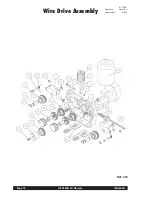
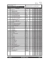
Страница 18: ...Page 18 REDI MIG 4D Remote IMA 600A Wire Drive Assembly AP 56 E Operative Apr 2004 Supersedes NEW Ref 410...
Страница 20: ...Page 20 REDI MIG 4D Remote IMA 600A Wire Drive Assembly AP 56 F Operative Apr 2004 Supersedes NEW Ref 410 2...
Страница 22: ...Page 22 REDI MIG 4D Remote IMA 600A NOTES...
Страница 23: ...IMA 600 REDI MIG 4D Remote Page 23 NOTES...


