Lincoln Electric INVERTEC 300TPX Скачать руководство пользователя страница 10

English  

English 

6

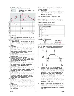
actual welding current following the instruction explained 
in the “Remote LED” description above. 
 
The left (V) Display can also shown the following set of 
characters: 


PREFLOW 


START CURRENT 


UPSLOPE 


BI-LEVEL 


FREQUENCY 


DUTY CYCLE 


BACKGROUND 


DOWNSLOPE 


CRATER 


POSTFLOW 


SPOT WELDING 


ERROR 


STORE 


RECALL 


SOFT 


CRISP 


PROGRAM 


The right (A) Display can also shown the following set of 
characters: 


01, …..10 

For program records 

01, ......99 

For error codes 

 
See “Operating Instruction” section for a detailed 
description of the functions described by these 
indications. 
 

Operating Instruction 


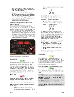
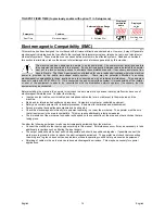
Stick (SMAW) Welding 

To select Stick welding: 

Action 

Visualization


Press MODE several times until the LED above lights up

 
When the Stick position is selected, the following 
welding features are enabled: 


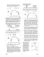
Hot Start:  This is a temporary increase in the output 
current during the start of the stick welding process.  
This helps ignite the arc quickly and reliably. 


Anti-Sticking:  This is a function which decreases 
the output current of the machine to a low level 
when the operator makes an error and sticks the 

electrode to the work piece.  This decrease in 
current allows the operator to remove the electrode 
from the electrode holder without creating large 
sparks which can damage the electrode holder. 


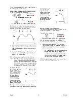
Auto Adaptive Arc Force:  this function increases 
temporary the output current, used to clear 
intermittent connections between the electrode and 
the weld puddle that occur during stick welding. 
 
This is an active control feature that guarantees the 
best arrangement between the arc stability and 
spatter presence.  The feature "Auto Adaptive Arc 
Force" has instead of a fixed or manual regulation, 
an automatic and multilevel setting: its intensity 
depends by the output voltage and it is calculated in 
real time by the microprocessor where are also 
mapped the Arc Force levels.  The control measure 
in each instant the output voltage and it determines 
the amount of the peak of current to apply; that 
value is enough to breaks the metal drop that is 
being transferred from the electrode to the 
workpiece as to guarantee the arc stability, but not 
too high to avoid spatters around the welding 
puddle.  That means: 


Electrode / workpiece sticking prevention, also 
with low current values. 

 Spatters 

reduction. 

 
The welding operations are simplified and the 
welded joins looks better, also if not brushed after 
the welding. 

 
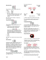
In Stick mode, two different setup are available: 


SOFT Stick:  For a welding with a low spatter 
presence. 


CRISP Stick (Factory Default):  For an aggressive 
welding, with an increased Arc stability. 

 
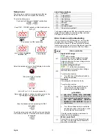
To switch between Soft  and Crisp: 


Action 


Visualization


At idle, before welding 

Voltage 

Press SEL 


Press SEL  


Wait 4s or start welding to 

store the changes 


 Voltage 

Содержание INVERTEC 300TPX

Страница 1: ...IM2041 03 2014 REV02 INVERTEC 300TPX 400TPX OPERATOR S MANUAL ENGLISH Lincoln Electric Bester Sp z o o ul Jana III Sobieskiego 19A 58 263 Bielawa Poland www lincolnelectric eu ...

Страница 2: ...hine INVERTEC 300TPX conforms to the following directives 2006 95 CEE 2004 108 CEE and has been designed in compliance with the following standards EN 60974 1 EN 60974 10 2007 15 02 2013 Paweł Lipiński Operations Director Lincoln Electric Bester Sp z o o ul Jana III Sobieskiego 19A 58 263 Bielawa Poland 07 11 ...

Страница 3: ...chine INVERTEC 400TPX conforms to the following directives 2006 95 CEE 2004 108 CEE and has been designed in compliance with the following standards EN 60974 1 EN 60974 10 2007 15 02 2013 Paweł Lipiński Operations Director Lincoln Electric Bester Sp z o o ul Jana III Sobieskiego 19A 58 263 Bielawa Poland 07 11 ...

Страница 4: ...e dealer For future reference record in the table below your equipment identification information Model Name Code Serial Number can be found on the machine rating plate Model Name Code Serial number Date Where Purchased ENGLISH INDEX Safety 1 Installation and Operator Instructions 2 Electromagnetic Compatibility EMC 14 Technical Specifications 15 WEEE 15 Spare Parts 15 Electrical Schematic 16 Sugg...

Страница 5: ...MAGNETIC FIELDS MAY BE DANGEROUS Electric current flowing through any conductor creates electric and magnetic fields EMF EMF fields may interfere with some pacemakers and welders having a pacemaker shall consult their physician before operating this equipment CE COMPLIANCE This equipment complies with the European Community Directives ARTIFICIAL OPTICAL RADIATION According with the requirements in...

Страница 6: ...ept to a minimum This machine has a protection rating of IP23 Keep it dry when possible and do not place it on wet ground or in puddles Locate the machine away from radio controlled machinery Normal operation may adversely affect the operation of nearby radio controlled machinery which may result in injury or equipment damage Read the section on electromagnetic compatibility in this manual Do not ...

Страница 7: ...tomatically turned ON and OFF in order to ensure the torch cooling When Stick welding mode is used the cooler will be OFF This machine does not include a cooled TIG torch but one may be purchased separately Refer to the accessories section for more information WARNING The Machine is provided with an electrical connection for the Coolarc unit on its rear side This socket is ONLY for the connection ...

Страница 8: ...rates in two different modes STICK and TIG STICK mode with a Remote command connected the output of the machine is ON A Remote Amptrol or Pedal are allowed trigger is ignored Connecting the Remote command excludes the Output Current Knob of the Machine s user interface Through the Remote command is available the full Output Current Range TIG mode in Local and remote mode the output of the machine ...

Страница 9: ...rrent knob sets the output current Memory Pushbuttons These pusbuttons allows to store M or recall M TIG welding programs 10 memory records P01 to P10 are available for the user To store or recall a record Store M Recall M 01 10 Store M Recall M Keep pushed for 4s The Memory pushbuttons are disabled during welding See List of parameters and Factory stored programs section below for a complete list...

Страница 10: ...rode holder Auto Adaptive Arc Force this function increases temporary the output current used to clear intermittent connections between the electrode and the weld puddle that occur during stick welding This is an active control feature that guarantees the best arrangement between the arc stability and spatter presence The feature Auto Adaptive Arc Force has instead of a fixed or manual regulation ...

Страница 11: ... the TIG arc will remain on for 3 seconds if the arc is not started in this time limit the trigger sequence must be restarted The HF arc start strength can be adjusted in the setup menu by changing the value of option 40 Six arc start strengths are available ranging from 1 smooth suitable for thin electrodes to 6 strong suitable for thick electrodes The default value for this option is 3 Spot TIG ...

Страница 12: ...rrent value after the Downslope For an explanation of the Crater operation refer to the trigger sequences explained below 7 POSTFLOW In the TIG welding modes this function controls the shielding gas Postflow time In Stick welding mode this is not used During welding the Sel pushbutton is enabled for the following functions Output current Only if Pulse Function is active is possible operates on the...

Страница 13: ...lding mode selected the following welding sequence will occur 1 Press and hold the TIG torch trigger to start the sequence The machine will open the gas valve to start the flow of the shielding gas After the preflow time to purge air from the torch hose the output of the machine is turned ON At this time the arc is started according to the selected welding mode After the arc is started the output ...

Страница 14: ... hold the TIG torch trigger another time to end the downslope time and maintain the output current at the Crater current When the TIG torch trigger is released the output will again increase to the Welding current like in step 4 to continue welding When the main part of the weld is complete go to step 3 As shown here again after the TIG torch trigger is quickly pressed and released from step 3A it...

Страница 15: ...machine wait for a few seconds then turn ON again If the error remains a maintenance is required Please contact the nearest technical service center or Lincoln Electric and report the error code displayed on the meter of the Front Panel Error code table 01 Input out of range LED is blinking Indicates that an Input Voltage Overrange protection is active the Machine restarts automatically when the I...

Страница 16: ...ance operations may vary in accordance with the working environment Any noticeable damage should be reported immediately Check cables and connections integrity Replace if necessary Keep clean the machine Use a soft dry cloth to clean the external case especially the airflow inlet outlet louvers WARNING Do not open this machine and do not introduce anything into its openings Power supply must be di...

Страница 17: ...round 30 10 90 step 1 Current selected value Downslope 0s 0 20s step 0 1s Current selected value s Crater 30 5 100 Current selected value A Postflow 10s 0 30s step 1s Current selected value s Stick Welding SOFT and CRISP programs Parameter Features Selectable Value Range Displayed parameter name Displayed value Soft Stick Hot start Anti Sticking and Arc Force are automatically adjusted by the mach...

Страница 18: ...uipment to ensure by consultation with the distribution network operator if necessary that the equipment may be connected Before installing the machine the operator must check the work area for any devices that may malfunction because of electromagnetic disturbances Consider the following Input and output cables control cables and telephone cables that are in or adjacent to the work area and the m...

Страница 19: ...0 C Storage Temperature 25 C to 55 C WEEE 07 06 English Do not dispose of electrical equipment together with normal waste In observance of European Directive 2002 96 EC on Waste Electrical and Electronic Equipment WEEE and its implementation in accordance with national law electrical equipment that has reached the end of its life must be collected separately and returned to an environmentally comp...

Страница 20: ...und cable 300A 50mm 2 10m GRD 400A 70 5M 400TPX Ground cable 400A 70mm 2 5m GRD 400A 70 10M 400TPX Ground cable 400A 70mm 2 10m GRD 400A 70 15M 400TPX Ground cable 400A 70mm 2 15m K10513 26 4 300TPX 400TPX Air cooled TIG torch LT 26 G 180A 4m K10513 26 8 300TPX 400TPX Air cooled TIG torch LT 26 G 180A 8m K10513 18 4 300TPX 400TPX Water cooled TIG torch LT 18 W 320A 4m K10513 18 8 300TPX 400TPX Wat...

Отзывы: