Lincoln Electric INVERTEC 160 TPX Скачать руководство пользователя страница 8

English 6 English 


WELDING SPARKS CAN CAUSE FIRE OR EXPLOSION:  Remove fire hazards from the welding area 
and have a fire extinguisher readily available.  Welding sparks and hot materials from the welding 
process can easily go through small cracks and openings to adjacent areas.  Do not weld on any tanks, 
drums, containers, or material until the proper steps have been taken to insure that no flammable or 
toxic vapors will be present.  Never operate this equipment when flammable gases, vapors or liquid 
combustibles are present. 


WELDED MATERIALS CAN BURN:  Welding generates a large amount of heat.  Hot surfaces and 
materials in work area can cause serious burns.  Use gloves and pliers when touching or moving 
materials in the work area. 


CYLINDER MAY EXPLODE IF DAMAGED:  Use only compressed gas cylinders containing the correct 
shielding gas for the process used and properly operating regulators designed for the gas and pressure 
used.  Always keep cylinders in an upright position securely chained to a fixed support.  Do not move or 
transport gas cylinders with the protection cap removed.  Do not allow the electrode, electrode holder, 
work clamp or any other electrically live part to touch a gas cylinder.  Gas cylinders must be located 
away from areas where they may be subjected to physical damage or the welding process including 
sparks and heat sources. 
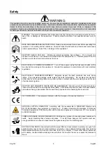
HF 

CAUTION:  The high frequency used for contact-free ignition with TIG (GTAW) welding, can interfere 
with the operation of insufficiently shielded computer equipment, EDP centers and industrial robots, 
even causing complete system breakdown.  TIG (GTAW) welding may interfere with electronic 
telephone networks and with radio and TV reception. 


SAFETY MARK:  This equipment is suitable for supplying power for welding operations carried out in 
an environment with increased hazard of electric shock. 

 
The manufacturer reserves the Right to make changes and/or improvements in design without upgrade at the same time 
the operator’s manual. 
 

Содержание INVERTEC 160 TPX

Страница 1: ...IM3156 11 2020 REV00 INVERTEC 160 TPX OPERATOR S MANUAL ENGLISH Lincoln Electric Bester Sp z o o ul Jana III Sobieskiego 19A 58 260 Bielawa Poland www lincolnelectric eu...

Страница 2: ...in the table below your equipment identification information Model Name Code Serial Number can be found on the machine rating plate Model Name Code Serial number Date Where Purchased ENGLISH INDEX Te...

Страница 3: ...Output Current I2 Output Voltage U2 230Vac 100 Stick 110A 24 4V 60 Stick 120A 24 8V 30 Stick 160A 26 4V 100 TIG 110A 14 4V 60 TIG 140A 15 6V 35 TIG 160A 16 4V OUTPUT RANGE Welding Current Range Open...

Страница 4: ...mode X STICK mode After 30 minutes of non working X Fan off The value of efficiency and consumption in idle state have been measured by method and conditions defined in the product standard EN 60974...

Страница 5: ...process gas usage depends on cross sectional area of the nozzle For commonly used torches Helium 14 24 l min Argon 7 16 l min Notice Excessive flow rates causes turbulence in the gas stream which may...

Страница 6: ...o and or television transmitters and receivers Computers or computer controlled equipment Safety and control equipment for industrial processes Equipment for calibration and measurement Personal medic...

Страница 7: ...electrical regulations ELECTRICALLY POWERED EQUIPMENT Regularly inspect the input electrode and work clamp cables If any insulation damage exists replace the cable immediately Do not place the electr...

Страница 8: ...s designed for the gas and pressure used Always keep cylinders in an upright position securely chained to a fixed support Do not move or transport gas cylinders with the protection cap removed Do not...

Страница 9: ...nput Supply From Engine Driven Generators The machine is designed to operate on engine driven generators as long as the auxiliary can supply adequate voltage frequency and power as indicated in the Te...

Страница 10: ...inside the Machine and the power consumption To restore the Machine simply restart to weld NOTE Green Mode long time condition each 10min of continuous Green Mode the fan runs for 1min D Gas Inlet Con...

Страница 11: ...n Trigger Mode Pushbutton This pushbutton changes the trigger sequence in TIG welding mode 2 step 4 step with restart This option is not selectable by the Trigger Pushbutton and if enabled operates wi...

Страница 12: ...ndications Operating Instruction Stick SMAW Welding To select Stick welding Action Visualization Press MODE several times until the LED above lights up When the Stick position is selected the followin...

Страница 13: ...ed for starting the TIG arc will remain on for 3 seconds if the arc is not started in this time limit the trigger sequence must be restarted The HF arc start strength can be adjusted in the setup menu...

Страница 14: ...t value after the Downslope For an explanation of the Crater operation refer to the trigger sequences explained below 7 POSTFLOW In the TIG welding modes this function controls the shielding gas Postf...

Страница 15: ...nce will occur 1 Press and hold the TIG torch trigger to start the sequence The machine will open the gas valve to start the flow of the shielding gas After the preflow time to purge air from the torc...

Страница 16: ...the downslope time and maintain the output current at the Crater current When the TIG torch trigger is released the output will again increase to the Welding current like in step 4 to continue weldin...

Страница 17: ...he option value on the right display is shown the option status Save the desired option by pressing the SEL pushbutton To exit the setup menu select the 00 option and keep the SEL button pushed for 5...

Страница 18: ...chine Turn OFF then ON the Mains Switch to restart the machine 10 Fan fault The cooling fan is blocked or faulty To restore the machine Turn OFF the Mains Switch then and check if the fan is being blo...

Страница 19: ...r any customer s particular purpose with respect to such information or advice As a matter of practical consideration we also cannot assume any respon sibility for updating or correcting any such info...

Страница 20: ...10 90 step 1 Current selected value of set current Downslope 0s 0 20s step 0 1s Current selected value s Crater 30 5 100 step 1 Current selected value of set current Postflow 5s 0 30s step 1s Current...

Страница 21: ...ing First read the Part List reading instructions above then refer to the Spare Part manual supplied with the machine that contains a picture descriptive part number cross reference REACh 11 19 Commun...

Страница 22: ...PROTIG NGS 10 EB 5m W000278395 2 PROTIG NGS 10 EB 8m W000278396 2 PROTIG NGS 20 EB 5m W000278397 2 PROTIG NGS 20 EB 8m W000278398 2 PROTIG NGS 30 EB 5m W000278399 2 PROTIG NGS 30 EB 8m W000278884 WTT...

Отзывы: