


English 8 English
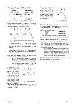
Connect the torch cable to the (-)
terminal of the machine and the work
clamp to the (+) terminal. Insert the
connector with the key lining up with
the keyway and rotate approximately
¼ turn clockwise. Do not over
tighten. Finally, connect the gas hose from the TIG torch
to the gas connector (B) on the front of the machine. If
necessary, an extra gas connector for the fitting on the
front of the machine is included in the package. Next,
connect the fitting on the back of the machine to a gas
regulator on the cylinder of gas to be used. An input gas
line and the required fittings are also included in the
package. Connect the TIG torch trigger to the trigger
connector (A) on the front of the machine.
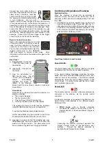
Remote Control Connection
Refer to the accessories section for a list
of remote controls. If a remote control is
used, it will be connected to the remote
connector on the front of the machine.
The machine will automatically detect the
remote control, turn on the REMOTE
LED, and switch to remote control mode. More
information on this mode of operation will be given in the
next section.
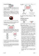
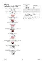
Rear Panel
A. Power Switch: It turns ON
/ OFF the input power to
the machine.
B. Input cable: Connect it to
the mains.
C. Fan: Do not obstruct or
filter the fan inlet. The
“F.A.N.” (Fan As Needed)
feature automatically
regulates the speed of
thefan. If the Machine
doesn’t weld for more than 5 minutes, it will enter
Green Mode.
Green Mode
Green Mode is a feature that puts the machine in a
stand-by condition:
The output is disabled
The fan is turned OFF
Only the Power ON LED remains ON.
A moving red dash is shown in the display
This reduces the amount of dirt that can be drawn
inside the Machine and the power consumption.
To restore the Machine simply restart to weld.
NOTE: Green Mode long time condition: each 10min
of continuous Green Mode the fan runs for 1min.
D. Gas Inlet: Connector for the TIG shielding gas. Use
the supplied gas line and connector to connect the
machine to the gas source. The gas source must
have a pressure regulator and flow gage installed.
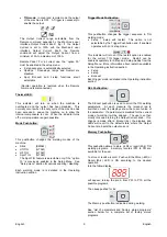
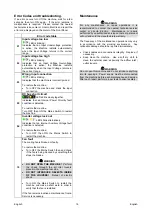
Controls and Operational Features
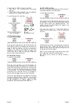
Machine Start-Up:
When the machine is turned ON an auto-test is
executed: during this test all the LEDs turn ON in
sequence; at the same time the displays show “333” and
then “888”.
The Machine is ready to operate when on the Front
Control Panel lights up the “Power ON” LED, the “A”
LED (placed on the middle of the synoptic) with one
of the LED of the Welding “MODE” command. This
is the minimum condition: depending by the welding
selection others LEDs may be ON.
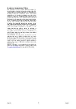
Front Panel Indicators and Controls
Power ON LED:
This LED blinks during the machine start-up and lights
up steadily when the machine is ready to operate.
If the Input Voltage Overrange protection becomes
active, the Power ON LED starts blinking and an error
code is shown on the displays. The machine restarts
automatically when the Input Voltage returns in the
correct range. For further detail read the Error Codes
and Troubleshooting section.
Remote LED:
This indicator will turn on when a Remote command is
connected to the machine via the remote control
connector.
If a Remote command is connected to the Machine, the
Output Current knob operates in two different modes:
STICK and TIG:
STICK mode:
with a Remote command
connected the output of the machine is ON. A
Remote Amptrol or Pedal are allowed (trigger is
ignored).
Connecting the Remote command excludes the
Output Current Knob of the Machine’s user
interface. Through the Remote command is
available the full Output Current Range.