A-1
INSTALLATION
A-1
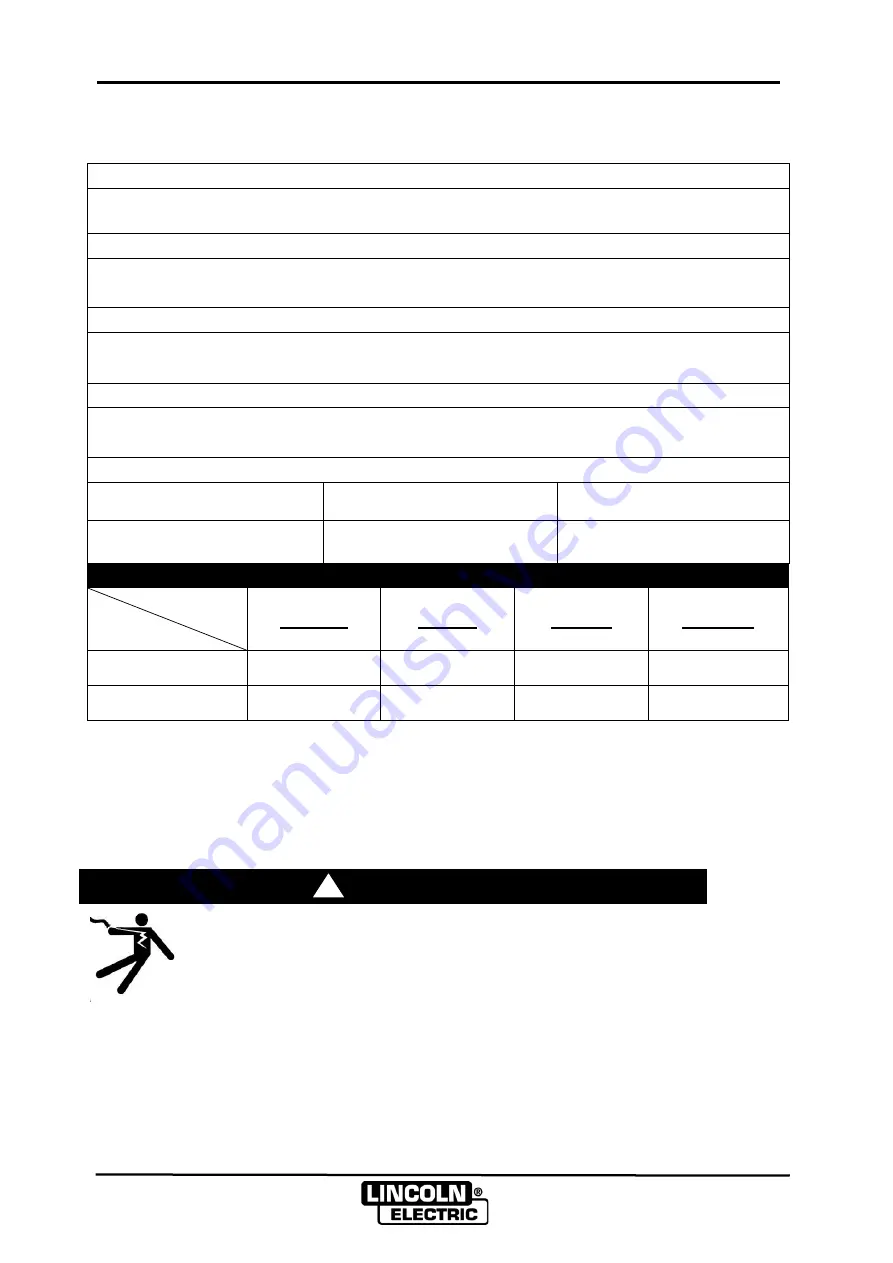
TECHNICAL SPECIFICATIONS
–
LWF
TM
Wire Feeders
MODEL
LWF
TM
-22, LWF
TM
-24 PLUS
INPUT POWER
Supplied by power source
RECOMMENDED WIRE SIZES
0.8mm, 1.0mm, 1.2mm, 1.4mm, 1.6mm,2.0mm
WIRE FEED SPEED
1.5 to 18m/min
WELDING WIRE SPOOL (Max. load 20 kg)
SHAFT DIAMETER
OUTSIDE DIAMETER
WIDTH
50mm
280mm
105mm
DIMENSIONS & WEIGHT (Without Welding Wire Spool)
Specification
Model
HEIGHT
WIDTH
DEPTH
WEIGHT
LWF
TM
-22
350mm
280mm
450mm
10.5kg
LWF
TM
-24 PLUS
350mm
280mm
450mm
12.5kg
Note: Please only use this wire feeder with specified power sources, otherwise no
output will be produced and the machine may be damaged.
SAFETY PRECAUTIONS
· Turn off the input power at the fuse box before working on other
equipment connected to the welding system at the disconnect
switch or fuse box before working on this equipment.
· Do not touch electrically hot parts.
!
WARNING
ELECTRIC SHOCK can kill.
·
Only qualified personnel should
perform this installation, mainte-
nance and troubleshooting work.
Содержание 76202
Страница 12: ...D 1 SCHEMATIC DIAGRAM D 1 ...


