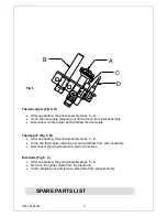
Lincat Silverlink 600 DC04 Скачать руководство пользователя страница 13

IS355 ECN3592 

13 

B

C

1

2

A

3

4

5

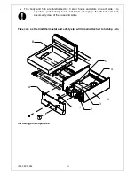
  The  body  and  hob  are  interlocked  by  3  steel  hooks  and  slots  on  each  side 

–  to 

separate,  push  hobtop  back  until  hooks  disengage  the  lift  hob  and  tank 
assumedly clear of the base and sides. 


Take care as the limit thermostat and safety stat will remain attached to hobtop 

– do 

not damage the capillaries. 


Содержание Silverlink 600 DC04

Страница 1: ...IS355 ECN3592 User Installation and Servicing Instructions Silverlink 600 Gas Fryers DF4 and DC04 Utensils Direct 01903 823888 www utensilsdirect co uk...

Страница 2: ...afety and operating instructions carefully before using this product Please pay particular attention to all sections of this User Guide that carry warning symbols and notices WARNING This is a Warning...

Страница 3: ...ments Do not obstruct or block the appliance flue Installation must include sufficient ventilation to prevent the occurrence of unacceptable concentrations of substances harmful to health in the room...

Страница 4: ...Butane 28 mbar Gas Consumption Total burner gas rate Natural 1 08 m 3 h 1 Total burner gas rate Propane 0 75 kg h 1 Total burner gas rate Butane 0 76 kg h 1 COMMISSIONING PREPARATION Remove all packa...

Страница 5: ...ue to the ceiling which must be of non combustible material This appliance is supplied with feet that should be fitted when it is to be mounted on either a counter top or tabletop If it is to be mount...

Страница 6: ...mply with local regulations When making the connection to the appliance secure the hexagon on the fitting to prevent rotation of the internal pipe work An isolating cock should be fitted into the supp...

Страница 7: ...e unit to the appropriate burner pressure See technical data table page 4 Adjustment to the burner pressure is made with burner lit and full on refer to operating instructions Adjustment of the burner...

Страница 8: ...mild detergent Turn the unit ON see Lighting Instructions and allow the water to boil for a short time Switch OFF and drain off the water Rinse the tank and dry thoroughly Run a small quantity of oil...

Страница 9: ...short period of time for the control to reset 8 To operate the main burner turn the thermostat control knob Fig 3 1 to the required temperature setting O F F PILOT O N O F F PILOT ON O F F P IL O T ON...

Страница 10: ...into both the inlet and outlet of the drain Wash all parts thoroughly Ensure all parts are thoroughly rinsed and dried To ensure there is no water left in the drain tube flush thoroughly with a small...

Страница 11: ...subsequently it cannot be removed by normal cleaning various branded cleansers are available such as Carb n Off which makes removal easy after overnight application Carb n Off is available from us Par...

Страница 12: ...ean or replace as necessary Check burner pressure and adjust where necessary See insulation instructions Clean pilot assembly and check that it is burning cleanly Ensure that the flue is clear Carry o...

Страница 13: ...d by 3 steel hooks and slots on each side to separate push hobtop back until hooks disengage the lift hob and tank assumedly clear of the base and sides Take care as the limit thermostat and safety st...

Страница 14: ...stat nut and withdraw phial from bracket Withdraw phial from tank Thermostat can now be removed Replace in reverse order ensuring correct phial location within the tank bracket Control thermostat Remo...

Страница 15: ...ions Remove screws from each side of valve support brackets Withdraw valve Replace in reverse order Reset burner pressure as per Installation instructions Separating Pilot assembly Fig 6 1 Remove the...

Страница 16: ...d withdraw thermocouple Thermopile Fig 6 B After separating the pilot assembly steps 1 4 Undo the thermopile retaining nut and withdraw from pilot assembly Disconnect thermopile lead at valve connecti...

Страница 17: ...s are listed with Lincat reference part number Piezo Ignitor not sparking Pilot burner will not light or stay lit Description Part number Piezo Igniter IG12 Igniter lead IG06 Igniter Electrode IG15 Pi...

Страница 18: ...open circuit If all of the above are OK the control valve may be faulty Check pilot jet for blockage and clean where necessary Check supply Check thermocouple voltage minium 15mV Is the oil temperatur...

Страница 19: ...ty for work carried out by other persons Please quote both the model and serial numbers from the data plate attached to the unit Give brief details of the service requirement If possible please quote...

Страница 20: ...IS355 ECN3592 Notes...

Отзывы: