


7
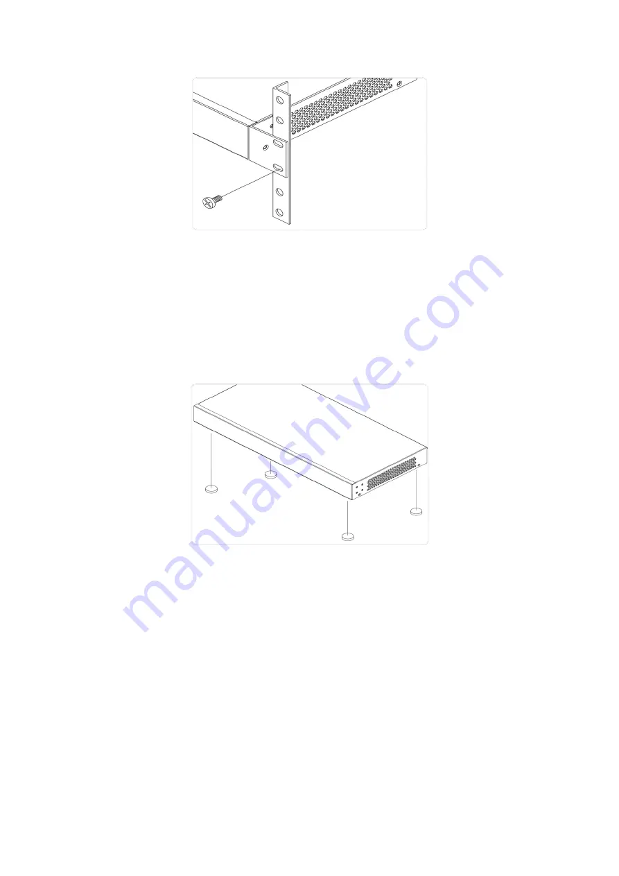
Mounting the Switch on Desk or Shelf
Step 1:
Verify that the workbench is sturdy and reliably grounded.
Step 2:
Attach the four adhesive rubber feet to the bottom of the switch.
Figure 5:
Attaching the Rubber Feet
Connecting the AC Power Cord
Step 1:
Connect the AC power cord to the AC power receptacle of switch.
Step 2:
Connect the other end of the AC power cord to the AC power outlet.
Step 3:
Check the SYS LED. If it is ON, the power connection is correct.
Figure 6:
Connecting AC power cord


