


2
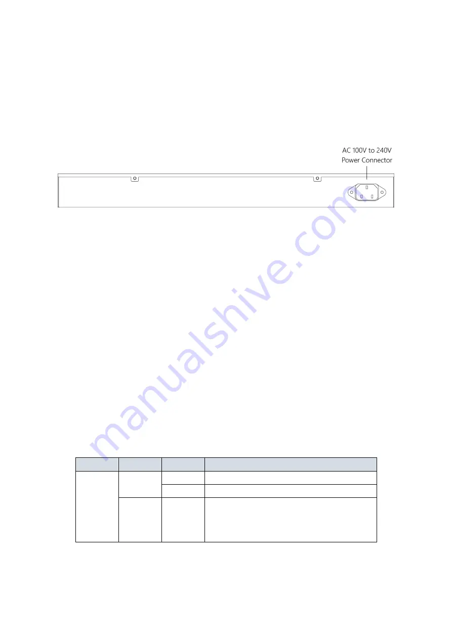
Rear View of the Switch
Figure 2:
Rear panel of the switch
LED Descriptions
The LEDs on the front panel provide users with switch status checking and
monitoring. There are three types of LEDs as follows:
•
System LED
indicates if the switch is powered up correctly or not, or,
indicates if there is a system alarm triggered for troubleshooting.
•
Mode LEDs
indicates the mode of all RJ45/SFP ports on the switch.
Users can press the Mode button sequentially to switch among the two
different modes (Link/Activity/Speed mode and PoE mode).
•
Port Status LEDs
indicates the current status of each RJ45/SFP port.
Users can check these LEDs to understand the port status in different
modes, after changing the mode by pressing Mode button.
The following table details the functions and descriptions of various LED
indicators.
Table 1:
System LED
LED
Color
State
Description
System
Green
On
The switch is powered ON correctly.
Off
The switch is not receiving power.
Red
On
An abnormal state, such as exceeding
operating temperature range, has been
detected in the switch.


