


TABLE OF CONTENTS
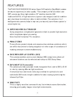
FEATURES
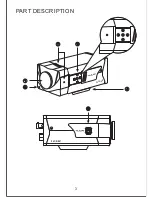
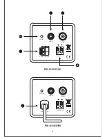
PART DESCRIPTION
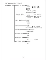
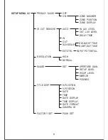
SETUP MENU TREE
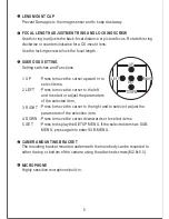
SETTING MENU AND FUNCTIONS
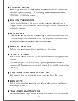
WHITE BALANCE
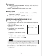
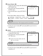
EXPOSE MODE AE SHUTTER (Expose Mode)
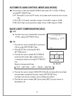
AUTOMATIC GAIN CONTROL MODE (AGC Mode)
BACK LIGHT COMPENSATION (BLC)
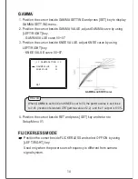
GAMMA
FLICKERLESS MODE
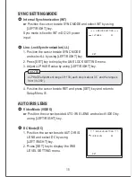
SYNC SETTING MODE
AUTO IRIS LENS
PRIVACY MASK
IR CUT REMOVE CONTROL
RESOLUTION MODE
IMAGE
TITLE DISPLAY
FACTORY DEFAULT
INSTALLATION
SPECIFICATIONS
1
3
7
9
9
11
13
13
14
14
15
15
16
17
19
20
21
22
23
27