8. Lightware Device Controller
UBEX series – Matrix Application Mode – User's Manual
69
8. Lightware Device Controller
UBEX series – Matrix Application Mode – User's Manual
69
MA
TRIX APPLIC
A
TION MODE
Applied F-series endpoint firmware package: v1.4.1 | Applied R-series endpoint firmware package: v1.4.1 | Applied MMU firmware package: v1.2.1 | LDC software: v1.34.0b2
8.4. Crosspoint Menu - Video Layer
8.4.1. Grid View
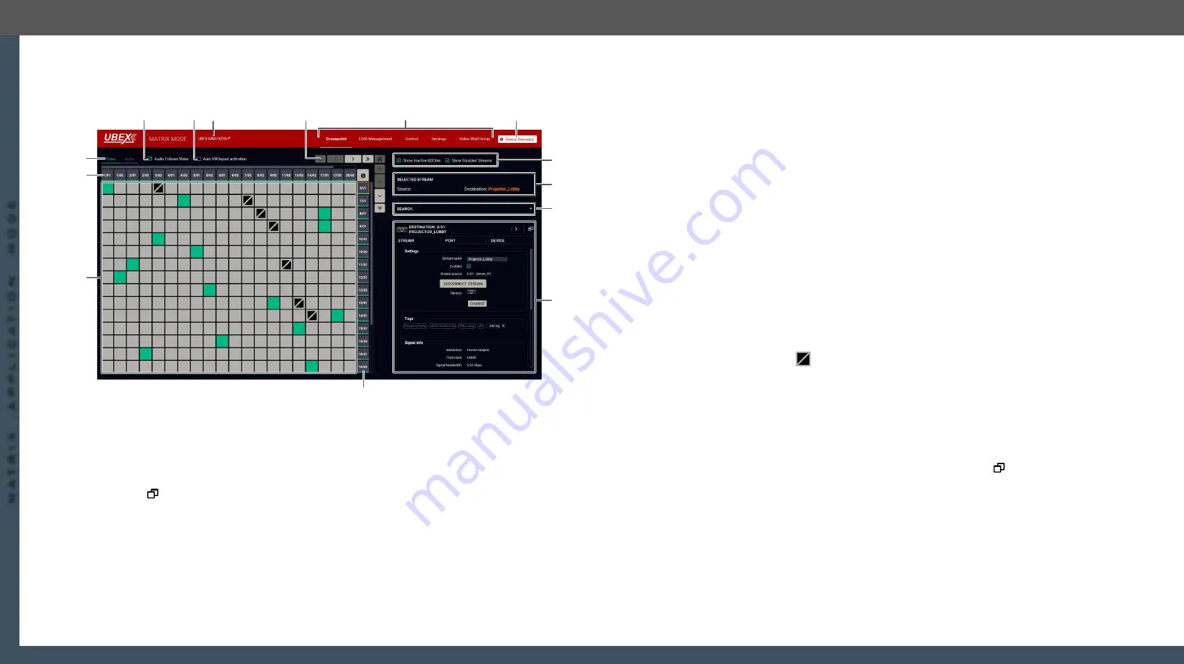
The grid view of the crosspoint menu - Video layer in Matrix mode
The Concept
The Crosspoint menu displays the
UBEX
matrix
in grid layout with all sources (the input ports of the
transmitters / transceivers) and destinations (the output ports of the receivers / transceivers). Clicking on
a source or destination panel the properties and settings of the selected item appear on the right side.
Clicking on the
icon the properties section opens in new window. The selected source/destination and
crosspoint are framed with orange.
#switch #crosspoint #gridview
Legend of the Crosspoint Menu
1
Device Discovery
Clicking on the button results in returning to the Device Discovery window. The
connection with the current device will be terminated.
2
Main menu
The available menu items (
,
Settings menu
) are displayed. The
crosspoint can be displayed in
Grid view
and
Tile view
. The
,
are available under the
Settings menu
.
1
4
2
q
r
e
w
7
8
6
5
t
9
3
3
Navigation
buttons
Clicking on the navigation buttons shows the available sources/destinations
and crosspoints which cannot be displayed within the recent window size. The
icon resets the grid to the default view.
4
Device label of
the MMU
The device label of the MMU is displayed here. It can be modified by the user to
any unique name by clicking on the
icon. The device label can be 39 characters
long and ASCII characters are allowed. Longer names will be truncated.
5
Auto VW layout
activation switcher
Auto
Video Wall
layout activation switcher, see the details in the
section.
6
Audio follows
video switcher
The explanation of the two available options is the following:
▪
Enabled
: the audio stream follows the video stream when the video
crosspoint is changed. Beside of this the audio streams can be switched
separately from the video streams on the Audio crosspoint tab.
▪
Disabled
: switching of a video stream does not effect the audio
crosspoint state.
7
Layer tabs
The
video
and the
audio
crosspoint panel can be selected on the tabs.
8
Source streams
Each tile represents a stream coming from one of the input ports of the
transmitter or transceiver. See the explanation of the source numbering in the
Source and Destination Numbering
9
Connections
The crosspoint connections can be selected in this table.
The tile means a denied connection (only for transceivers). The
explanation is the input port of the transceiver cannot be selected to the
output port of the same transceiver.
q
Destination
streams
Each tile represents an output port of a receiver or transceiver. See the
explanation of the destination numbering in the
w
Properties
window
The properties, available settings, and status information of the selected
source or destination are displayed in this section. Three tabs are available:
Stream
,
Port
, and
Device
. Clicking on the
icon the properties section
opens in new window. See more details about the source ports in the
section and about the destination ports in the
Video Destination Port Properties Window
section.
e
Search field
Streams, ports, and devices can be searched in the field. See the details in the
section.
r
Selected /
Highlighted
streams
Showing the currently selected connections. Move the cursor above the
desired crosspoint and the names of the source and destination are displayed
in the field.
t
Show Inactive
UBEXes / Disabled
Streams switchers
When they are enabled, the inactive devices / disabled streams are shown in
the crosspoint table. When they are disabled, the inactive devices / disabled
streams are hidden.


