LIGHT PROGRESS
STICK-ST [Eng.]
Rev. 2 Oct 2020
Page
7
of
15
INSTALLATION
Take the device to the room to be disinfected, and place it in a position. In case of more than one device, you should
place them so that UV irradiation is uniformly distributed avoiding creating shaded areas.
The area/space covered by the UV-STICK devices are shown in Table 1. Final disinfection results are case
dependent on the amount of germs coming in from the external environment.
WARNING!!!
Remember to switch on the device ONLY IF there is adequate shielding and no accidental
exposure to rays by the personnel.
To avoid exposure to UV-C rays please provide a total shielding of the modules or enable the automatic OFF devices
at the entry doors in the environment treated. There must be no direct irradiation of the personnel.
To shield the devices, materials with opaque surfaces such as stainless steel or aluminium can be used, but also
transparent materials such as glass or Lexan®; to have further information please contact us.
To improve safety, we suggest you to add light signs or signboards to report the potential danger.
SCHEDULING
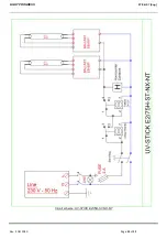
UV-STICK -E2/75H-ST-NX-NT
With timer for ignition delay and treatment duration setting.
Ensure Safety Glasses are worn before continuing:
Insert the plug into the wall socket and turn the device on using the switch on the back of the control unit. The green
control light of the switch will confirm the activation of main power source.
It is possible to set treatment duration and ignition delay, enabling time to comfortably step back from the device and
avoid accidental expositions to UV-C rays.
The ranges of both adjustments can vary from a minimum of a second to a maximum of 50 hours.
Two settings must be made:
A. IGNITION DELAY DURATION
(before sterilization starts)
B.
TREATMENT DURATION
Proceed with the following steps: (see picture 7)
1) The desired range (scale) of the two
chronometers must be set. To set the range of the
chronometers, turn the Phillips screws located at
the bottom left on the chronometer. For ignition
delay, turn screw 1 (Delay).
For treatment duration, turn screw 2 (Timer).
2) The desired durations can now be set acting
on the setting head of each chronometer. To set
ignition delay duration, turn left setting head
(Delay).
To set treatment duration, turn right setting head
(Timer). We recommend a value between 20 min.
and 2-3 hours.
3) Once setting is completed, push the
START/STOP button to begin the program. The
button will light up and the program will start.
Fig 7
4) After the end of the cycle press START/STOP
again (the light will turn off) to finish the
operation.
1
2

