LIGHT PROGRESS
STICK-ST [Eng.]
Rev. 2 Oct 2020
Page
6
of
15
ASSEMBLY
Handle with care. Verify the integrity of the packaging, and please be careful not to damage the contents when using
sharp blades or cutters to open the box.
Remove the unit from the box. Inspect it immediately to ensure that no damage has occurred during transport. Before
installation and use of the device please READ CAREFULLY THE SECURITY WARNINGS and all instructions that
follow.
For packaging and transport reasons, the entire unit
comes in two parts:
(1) metal stand with wheels, and
(2) UV unit.
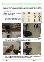
It is necessary to assemble the UV unit to the base with
the supplied screw kit (Picture 2).
We recommend the following assembly procedure:
- Place the base plate vertically, like shown on
Picture 3, with semicircular side upwards. Align
the top hole with the corresponding hole on the
unit, insert the hex head screw then tighten by
hand or with the aid of a key. Repeat with the
bottom hole (Picture 4).
Pic. 2
Pic.3
Pic.4
- On the other side of the plate, insert the two hexagonal socket head cap screws into the holes at the bottom of
the control unit (Picture 5), then tighten it with the self-locking nuts (Picture. 6).
Pic.5
Pic.6
- Firmly tighten the four screws. It is now possible to place the device on its wheels in vertical position, and to
connect the power cable to the dedicated socket on the back of the control unit.

