Lamp
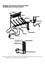
BURNER SYSTEM ILLUSTRATION WIRE
CONNECTING SYSTEM LAYOUT
Rotisserie burner
assembly
Electrode wire
Rotisserie burner
valve assembly
Metal hose
Hose
Main burner
valve assembly
Battery compartment
LED switch
Lamp switch
Transformer
Note: The grounding wire and igniter switch wire must be inserted into the positions as figure shown.
The other wires can be inserted into any other positions.
Side burner
Side valve assembly
Electrode wire (thick one)
Grounding wire (in black color, 1pc)
Main burner igniter wire
(in red color, 5pcs)
Igniter switch wire
(in white color, 1pc)
Содержание SRGG51103
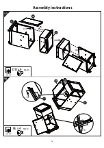
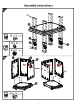
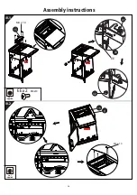
Страница 21: ...5 1 5 2 Assembly instructions 21 25 38 23 37 18 KK x 1 DD x 9 M6x14 not supplied DD DD ...
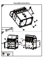
Страница 23: ...7a Assembly instructions 23 BB x 1 CC x 2 M6x12 not supplied 19 25 19 25 7 M6 x 30 CC ...
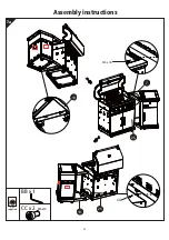
Страница 26: ...Assembly instructions 26 EE x 2 M4x10 not supplied 10 1 not supplied 15 9 10 2 M4 x 10 15 M4 x 10 EE 41 43 42 ...
Страница 27: ...Assembly instructions 27 11a 1 11b 2 1 2 3 32 8 3 5 5 ...

