background image

26


EVOS

®

 FL and EVOS

®

 FL Color User Guide


Saving 


Basic Saving 


Note:

 If there is no USB flash drive or network connection in place, a 

warning message will appear. Insert a USB flash drive, then click the 

Cancel

 button to clear the message. 


1.


After capturing your image (see “Basic Operations” on page 17), click the 

Save

 button. The Save File dialog box will appear. 

2.


Click in the Save File Name text field, then type your desired file name and 
click the 

Accept

 button. 


Note:

 To overwrite a file, simply select the name of the file from the saved 

files list, instead of clicking on the Save File Name text field. A Save As 
confirmation dialog box will pop up. It is not possible to recover an 
overwritten file. 


3.


To select the destination for the new image, click on the name of a folder in 
the Save Folder list. 


Note:

 To create a new folder, first click the name of the parent folder, then 

click the 

New Folder

 button to enter a folder name. 


4.


Select a file format (.tif, .png, .jpg or .bmp) from the File Type drop-down 

menu. 


Note:

 To save a 16-bit image, select .tif or .png and ensure the Scalebar and 

Color options are off. File types .jpg and .bmp (as well as images of all 
types with the Scalebar, or Color options engaged) only save at an 8-bit 
depth. 


5.


Click the 

Save

 button to save the file. 


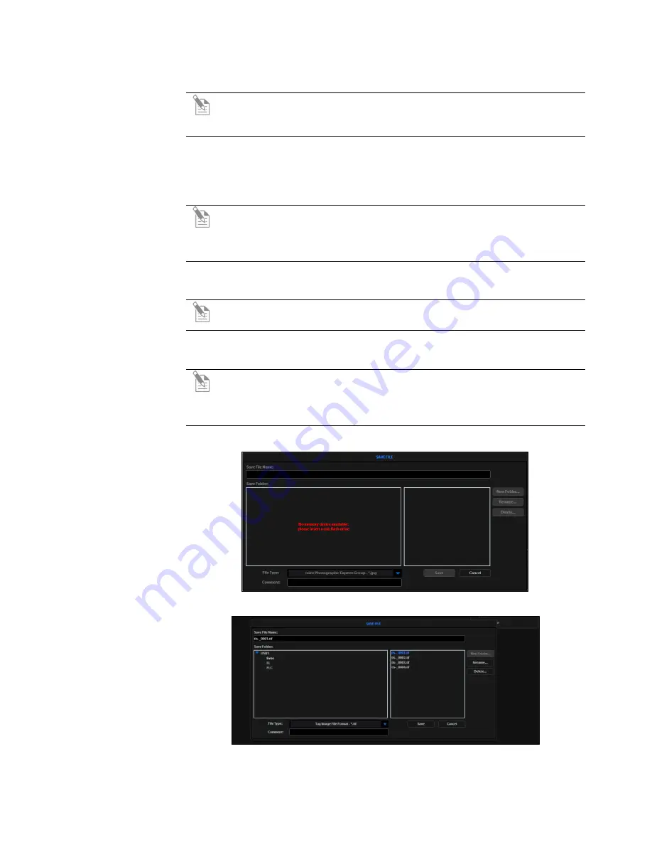
Figure 16

 Save File information message 


Figure 17

 Save File dialog box 


Содержание EVOS FL

Страница 1: ...L EVOS FL Color Imaging Systems for Fluorescence and Transmitted Light Applications Catalog Numbers AMF4300 AMEFC4300 Publication Number MAN0007988 Revision 1 0 For Research Use Only Not for use in diagnostic procedures ...

Страница 2: ...oduct conveys to the purchaser the limited non transferable right to use the purchased amount of the product only to perform internal research for the sole benefit of the purchaser No right to resell this product or any of its components is conveyed expressly by implication or by estoppel This product is for internal research purposes only and is not for use in commercial applications of any kind ...

Страница 3: ...14 Pins Locks and Power Supply 15 Ports and Shields 16 3 Basic Operations 17 Brightfield Phase Operations 17 Fluorescence Operations 19 4 Advanced Operations 20 Transfection 20 Time Lapse 21 5 Working with Images 23 Live Captured Zoom and Scalebar Option 23 Cell Counting 24 Saving 26 Image Review 29 6 Optional Settings 30 Date Time Settings 30 Network Settings 31 Login Settings 34 7 Maintaining th...

Страница 4: ... 43 Safety Conventions Used in this Document 44 Symbols on Instruments 45 Safety Labels on Instruments 47 General Instrument Safety 48 Chemical Safety 49 Chemical Waste Safety 50 Electrical Safety 51 Physical Hazard Safety 52 Biological Hazard Safety 52 Safety and Electromagnetic Compatibility EMC Standards 53 Documentation and Support 54 Obtaining Support 54 ...

Страница 5: ...ty but have the advantage of being able to differentiate structures by color in transmitted light for example imaging stained tissue samples Safety Alert Words Four safety alert words appear in Life Technologies user documentation at points in the document where you need to be aware of relevant hazards Each alert word IMPORTANT CAUTION WARNING DANGER implies a particular level of observation or ac...

Страница 6: ...Figure 1 FL footprint Power Input Jack Y Axis Stage Brake Power Switch Focusing Knobs USB and DVI Ports Objective Selection Wheel Coarse Stage Positioning Knobs Light Cube Selection Lever Stage X Axis Knob Phase Annuli Selector X Axis Stage Brake Condenser Slider Slot Stage Y Axis Knob ...

Страница 7: ...agnifications Y axis Stage Brake To secure the stage in place for time lapse image captures tighten the Y axis stage brake Focusing Knobs Use the focusing knobs to bring the specimen into focus Objective Selection Wheel Turn the objective selection wheel to change magnifications The objective turret will click into place at each position Note An exclamation point will appear instead of the current...

Страница 8: ...f you do not have your distributor information refer to the EVOS FL Imaging System product page at www lifetechnologies com evosfl or contact Technical Support see page 54 for instructions on how to perform the software updates Figure 3 UI Controls Reference Channel Indicator Bar with the Active Channel highlighted Exposure Time Slider Image Capture Button Login Button Color Option Control Bar Tab...

Страница 9: ... manually select the exposure time that will be used during image capture Overlay Use the Overlay tab to select and overlay multiple fluorescence channels as a single multicolor image Overlay Color Dialog Box The Color Adjustment button left control bar opens the Adjust Color dialog box where you can fine tune your live image Brightness Contrast Saturation and Hue prior to capture Light ON OFF But...

Страница 10: ...ed Note A red USB icon indicates that the current image has not been saved Info Display Bar Shows the following context sensitive data in the Find Focus and Actual tabs Intensity Max and Min Ratio Max to Min Cursor position Note In Overlay the info display shows the Quick Save option with the Quick Save file name and the current objective selected The color camera version shows the QuickSave optio...

Страница 11: ...nser Working Distance 60 mm Mechanical Glide Stage XXY axis fine positioning controls 28 3 mm 1 11 per rotation 110 mm 110 mm 4 3 4 3 range of motion XXZ axis focusing controls 480 µm rotation XX Interchangeable vessel holders available for most common shapes and sizes LCD Display 15 color 1024 768 pixels adjustable tilt Image Acquisition Onboard microprocessor built in software for image acquisit...

Страница 12: ...nical Support see page 54 EVOS FL or EVOS FL Color Imaging System Power Adapter and Power Cord Dust Cover USB Flash Drive preconfigured with instrument documentation Accessories Kit Mouse Sliders Light Shield Box UV Shield Assembly includes mount shield screws and L shaped hex key Light Cube Access Cover includes LED light cube installation tool must be installed before using the EVOS LED Light Cu...

Страница 13: ...ds under the support and place on a level surface away from vibrations from other pieces of equipment Figure 4 Grasp under support arm with both hands to lift EVOS Note Be sure to set aside packaging and foam for future transport and storage To move or transport the instrument the stage pin and light cube lock must be re installed Always be sure the instrument is properly cushioned and braced to p...

Страница 14: ...System should not be subjected to UV sterilization UV degrades many materials including plastic Damage from UV exposure is not covered under the manufacturer s warranty Desktop Setup 1 Lift the EVOS FL Imaging System as before see page 13 and place it on the table 2 Tilt the LCD monitor upright 3 Remove the stage pin connect the power cord mouse and if desired keyboard Hood Setup Note The EVOS FL ...

Страница 15: ...to the light cube lock which is centered under the back of the stage 2 Loosen the thumbscrew to remove the light cube lock making sure to store the light cube lock for future use Always re secure the light cube lock before moving transporting the instrument 3 Place the light cube access cover into the opening and tighten thumbscrew IMPORTANT Before changing light channels ALWAYS verify the light c...

Страница 16: ...on the instrument UV Shield Note The UV Shield is provided as a safety feature and should always be installed whenever the unit is in operation The UV shield is removable for access to the condenser sliders used in transmitted light mode Simply unhook it from the screws on the UV mount Secure the shield in place as shown in Figure 6 below Figure 6 UV shield in place Condenser Shield The Condenser ...

Страница 17: ...ument 2 Move light cube selection lever towards you until the active channel on screen reflects transmitted 3 Turn the phase annuli selector to the position that corresponds to the selected objective and contrast method 4 Insert the desired condenser slider into the slot on the condenser assembly for optimal image quality Note A variety of sliders can be inserted into the instrument condenser to i...

Страница 18: ...exposed pixels will appear red to obtain the maximum level of brightness without any overexposed areas dim the illumination until the red highlights disappear To disable this feature go to the Basic Tab found under the settings menu Figure 9 Figure 9 Settings Basic Tab 8 Click the Capture button to acquire the image ...

Страница 19: ...above to capture an image in each desired channel i e GFP RFP DAPI 2 Click The overlay tab to display the multi channel image in color Note See Working with Images page Error Bookmark not defined for more information Helpful Tips To display the image with pseudo colors turn on the color option To display the image in grayscale turn off the color option this often shows more detail than a color ima...

Страница 20: ... adjust focus if necessary before capturing the transmitted light channel Figure 10 Transfection Tool 3 Click the Run Sequence button Note You will need to check the focus and lighting prior to running the sequence The sequence always starts with the fluorescence channel and finishes with the transmitted light channel 4 If the Pause option is selected adjust focus and click the Continue button Not...

Страница 21: ...the approximate number of images Figure 11 1 Once the specimen is focused and ready tighten the stage brakes to prevent the stage from drifting during the session 2 Open the Toolbar and select the Time Lapse tool 3 Click the Interval text field and enter a numeric value defines the frequency of image capture Note Use the drop down menu to choose a unit of measure for example minutes for the interv...

Страница 22: ...torage device and or change the parameters selected Click the Start button to begin the time lapse session The Time Lapse Progress popup will display as long as the session is active Figure 12 Figure 12 Time Lapse Progress Popup Time Lapse Progress Screen Key Interval Time remaining before next image is captured Duration Time remaining before session is complete Disk Space Available disk space rem...

Страница 23: ...edges of the screen as close to the center as possible You may re center repeatedly Captured Zoom Feature Capturing and saving a zoomed image will result in a file showing the actual magnification not the zoomed magnification If the scale bar is active it will appear in the saved file To double the digital zoom level double click again on any point in the enlarged image You can continue double cli...

Страница 24: ... 1 Acquire an image See Basic Operations page 17 2 Open the Toolbar and expand the Count tool Figure 13 3 Click in a text field under the Labels section to name a label You may use up to 6 labels Figure 13 Figure 13 Count Tool 4 Under Settings you may choose a grid size in the drop down menu or leave the Show Grid option inactive 5 Click on the radial button next to the desired label and left clic...

Страница 25: ... a tag select and drag it Left click anywhere else onscreen to deselect 7 To delete a tag select the Delete radial button under the Mode section then left click the tag to be deleted You may also use the Clear All button to delete all tags for all labels 8 To save an image showing the tags on screen and data recorded in the count tool select the Save Image with Toolbar option and click the Save bu...

Страница 26: ...n the Save File Name text field A Save As confirmation dialog box will pop up It is not possible to recover an overwritten file 3 To select the destination for the new image click on the name of a folder in the Save Folder list Note To create a new folder first click the name of the parent folder then click the New Folder button to enter a folder name 4 Select a file format tif png jpg or bmp from...

Страница 27: ...pecify the settings and select the QuickSave option and the system will save each image with a single click of the Save button 1 Click the Settings button to open the Settings dialog box and then select the QuickSave tab Figure 18 Figure 18 QuickSave Option 2 Click in the Base Filename text field and enter a name that describes the imaging session The orange Next file name will reflect the informa...

Страница 28: ... color camera version displays the QuickSave option in all tabs Figure 16 10 After acquiring an image see Basic Operations on page 17 click Save The image will be saved as specified in the QuickSave settings Figure 19 Figure 19 Settings QuickSave Tab ...

Страница 29: ...the desired file Click the image to select it The selected file name appears orange 5 Click the View File button to display the image in the image review window This button toggles between View File and Hide File Hiding the file closes the image review window Note Double clicking the thumbnail image will also toggle between displaying and hiding the file 6 To zoom the image in the review window do...

Страница 30: ...me information on saved image files verify the EVOS date time settings before your capture session 1 Click the Settings button to open the Settings dialog box and then select the Service tab Figure 22 2 Click the Change button under Date and Time 3 In the Date and Time popup use the arrows and the drop down menus to set the time date and time zone then click OK Figure 23 4 Click OK in the Settings...

Страница 31: ...g items not included Ethernet Cable USB to Ethernet Adapter Note For best results use one of these compatible USB to Ethernet adapters Belkin model F5D5050 Cisco Linksys model USB300M D Link model DUB E100 TRENDnet model TU ET100C TRENDnet model TU2 ET100 Logging onto the Network 1 Verify the instrument is powered on and the network cable is plugged into the correct jack and connected via the adap...

Страница 32: ...ote If a domain server or shared file appears on the file tree without a triangle icon and you are not able to expand or open it your permission to access that item is restricted Figure 26 Refreshing the network connection 5 Enter your network domain user name and password in the login fields and select a server to view the top level of shared folders on that server You may now navigate below the ...

Страница 33: ...wse popup Figure 29 Figure 29 QuickSave Browse Popup Note All selected network destinations as well as any USB flash drives currently plugged in will appear in the Browse popup These locations will also be available in the Save dialog box and through the Browse button in the Time Lapse and Image Review tools Helpful Tips EVOS will try to connect for about 30 seconds If there is a problem with the ...

Страница 34: ... and adjust settings as desired When you switch off EVOS will save your settings to memory Figure 31 Note To copy an existing profile highlight the profile in the user list select the Copy from name option and click the Add button The virtual keyboard will pop up so you can name the new profile Figure 31 Login Dialog Box 3 To remove a user profile highlight it and click the Remove button A confirm...

Страница 35: ... screen 3 Clean the LCD display with a non alcohol based cleaner made for flat panel displays IMPORTANT Do not spray cleaning fluid directly onto the screen as it may drip into the display or optics 4 Lightly wipe the working surfaces stage top focusing knobs objective selection wheel housing of the instrument with paper towels or Kimwipes dampened with 70 ethanol or 4000 ppm hydrogen peroxide H2O...

Страница 36: ...vely you can get the latest software and documentation updates from your local EVOS distributor or by contacting Technical Support page 54 Install Software Update 1 Plug the USB stick into the data port on the lower right side of the EVOS support arm 2 Click the Settings button to open the Settings dialog box and then select the Service tab Note Changing settings in the Service tab will affect the...

Страница 37: ...ass 3B ultraviolet LED for the DAPI channel Before changing LED light cubes power off the instrument 1 Turn the power switch to the OFF position before removing or changing light cubes Figure 33 Power switch 2 Move the stage back to allow access to the light cube access cover centered under the back of the stage Figure 34 Figure 34 Light Cube Access Cover under stage 3 Loosen the thumbscrew to rem...

Страница 38: ...lightly toward you and lift out gently then remove tool from cube 8 Attach the tool to the new light cube and then lower the cube into position so that the electronic connection aligns properly facing the back of the instrument and the cube sits squarely in place 9 Use the light cube tool to gently tighten the 2 slotted screws so that the screw heads sit flush with the ridges on the light cube Fig...

Страница 39: ...ttings button to open the Settings dialog box and then select the Channels tab Figure 38 Figure 38 Settings Button 2 Select the appropriate color from the drop down menu for each light cube you wish to customize Figure 39 3 Click OK to accept the custom color assignments The display change will take effect with the next image acquired in the customized channel Figure 39 Assigning custom channel di...

Страница 40: ...n s thickness is even Trouble focusing on coverslipped specimen on standard slide Place the slide so the coverslip is facing up long working distance objectives require a thick optical substrate and image best through 1 0 to 1 5 mm of glass or plastic LCD screen is black Click the LIGHT ON button onscreen Move objective selection wheel so that light shines through objective Verify that the phase a...

Страница 41: ...first scalebar is only available after capturing an image Save button does not respond when clicked Click capture first it is only possible to save an image that is captured The USB icon on the Save button is red when there is a captured image to save DVI output does not work on an external LCD monitor or projector Power the instrument off check the cable connections and power on the instrument Ve...

Страница 42: ...n Check stage brakes on the stage knobs and loosen as needed Vessel does not sit securely on moving stage Use the correct vessel holder for the application refer to the EVOS Vessel Holders spec sheet included on the USB flash drive Mechanical stage drifts during time lapse sessions Tighten the stage brakes on the stage knobs securely before starting a time lapse session Mechanical stage tension is...

Страница 43: ...cs Safety conventions used in this document Symbols on instruments Safety labels on instruments General instrument safety Chemical safety Chemical waste safety Electrical safety Physical hazard safety Biological hazard safety Workstation safety Safety and electromagnetic compatibility EMC standards ...

Страница 44: ...ally hazardous situation that if not avoided may result in minor or moderate injury It may also be used to alert against unsafe practices WARNING Indicates a potentially hazardous situation that if not avoided could result in death or serious injury DANGER Indicates an imminently hazardous situation that if not avoided will result in death or serious injury This signal word is to be limited to the...

Страница 45: ...the Standby condition Hazardous voltage may be present if this switch is on standby Indicates the On Off position of a push push main power switch Indicates a terminal that may be connected to the signal ground reference of another instrument This is not a protected ground terminal Indicates a protective grounding terminal that must be connected to earth ground before any other electrical connecti...

Страница 46: ...ate caution Indicates the presence of a laser inside the instrument and to proceed with appropriate caution Indicates the presence of moving parts and to proceed with appropriate caution Indicates the presence of a biological hazard and to proceed with appropriate caution Indicates the presence of an ultraviolet light and to proceed with appropriate caution Environmental Symbols on Instruments The...

Страница 47: ... élimination des déchets DANGER High voltage DANGER Haute tension WARNING To reduce the chance of electrical shock do not remove covers that require tool access No user serviceable parts are inside Refer servicing to Life Technologies qualified service personnel AVERTISSEMENT Pour éviter les risques d électrocution ne pas retirer les capots dont l ouverture nécessite l utilisation d outils L instr...

Страница 48: ...of the computer and or the monitor moving them may require two or more people Things to consider before lifting the computer and or the monitor Make sure that you have a secure comfortable grip on the computer or the monitor when lifting Make sure that the path from where the object is to where it is being moved is clear of obstructions Do not lift an object and twist your torso at the same time K...

Страница 49: ...handles locked in the upright position Wear appropriate eyewear clothing and gloves when handling reagent and waste bottles General Safety Guidelines To minimize the hazards of chemicals Read and understand the Safety Data Sheets SDSs provided by the chemical manufacturer before you store handle or work with any chemicals or hazardous materials See Safety Data Sheets SDS on page 54 Minimize contac...

Страница 50: ... clothing For additional safety guidelines consult the SDS Minimize the inhalation of chemicals Do not leave chemical containers open Use only with adequate ventilation for example fume hood For additional safety guidelines consult the SDS Handle chemical wastes in a fume hood After emptying the waste container seal it with the cap provided Dispose of the contents of the waste tray and waste bottl...

Страница 51: ...eplace fuses only with fuses of the type and rating specified for the instrument Power DANGER ELECTRICAL HAZARD Grounding circuit continuity is vital for the safe operation of equipment Never operate equipment with the grounding conductor disconnected DANGER ELECTRICAL HAZARD Use properly configured and approved line cords for the voltage supply in your facility DANGER ELECTRICAL HAZARD Plug the s...

Страница 52: ...cations In the U S U S Department of Health and Human Services guidelines published in Biosafety in Microbiological and Biomedical Laboratories stock no 017 040 00547 4 available at www cdc gov Occupational Safety and Health Standards Bloodborne Pathogens 29 CFR 1910 1030 www access gpo gov nara cfr waisidx_01 29cfr1910a_01 html Your company s institution s Biosafety Program protocols for working ...

Страница 53: ... CSA CSA America ANSI ASME ASSE ASTM NSF and UL European Safety and EMC Standards The CE M ark symbolizes that the product conforms to all applicable European Community provisions for which this marking is required Operation of the instrument is subject to the conditions described in this manual The protection provided by the instrument may be impaired if the instrument is used in a manner not spe...

Страница 54: ...ions handbooks certificates of analysis citations and other product support documents Obtain information about customer training Download software updates and patches Safety Data Sheets SDS Safety Data Sheets SDSs are available at www lifetechnologies com sds IMPORTANT For the SDSs of chemicals not distributed by Life Technologies contact the chemical manufacturer Limited Product Warranty Life Tec...

Страница 55: ...ers 5791 Van Allen Way Carlsbad CA 92008 USA Phone 1 760 603 7200 Toll Free in USA 800 955 6288 For support visit lifetechnologies com support or email techsupport lifetech com lifetechnologies com 8 April 2013 ...

Отзывы: