background image


1. Safety and EMC instructions


Please read carefully the following user manual and the safety instructions before installing the unit or using the 
unit! 

1-1. Transportation and Storage 


Please transport the UPS system only in the original package to protect against shock and impact. 


The UPS must be stored in the room where it is ventilated and dry. 

1-2. Preparation 


Condensation may occur if the UPS system is moved directly from cold to warm environment. The 
UPS system must be absolutely dry before being installed. Please allow at least two hours for the 
UPS system to acclimate the environment.   


Do not install the UPS system near water or in moist environments. 


Do not install the UPS system where it would be exposed to direct sunlight or nearby heater. 


Do not block ventilation holes in the UPS housing. 

1-3. Installation 


Do not connect appliances or devices which would overload the UPS (e.g. big motor-type 

equipment)) to the UPS output sockets or terminal.   


Place cables in such a way that no one can step on or trip over them.   


Do not block air vents in the housing of UPS. The UPS must be installed in a location with good 

ventilation. Ensure enough space on each side for ventilation.   


UPS has provided earthed terminal, in the final installed system configuration, equipotential earth 

bonding to the external UPS battery cabinets. 


The UPS can be installed only by qualified maintenance personnel. 


An appropriate disconnect device as short-circuit backup protection should be provided in the 

building wiring installation. 


An integral single emergency switching device which prevents further supply to the load by the UPS 

in any mode of operation should be provided in the building wiring installation.   


Connect the earth before connecting to the building wiring terminal.   


Installation and Wiring must be performed in accordance with the local electrical laws and 

regulations.   

1-4. Operation 


Do not disconnect the earth conductor cable on the UPS or the building wiring terminals in any time 

since this would cancel the protective earth of the UPS system and of all connected loads.   


The UPS system features its own, internal current source (batteries). The UPS output sockets or 

output terminal blocks may be electrically live even if the UPS system is not connected to the 

building wiring outlet.   


In order to fully disconnect the UPS system, first press the “OFF” button and then disconnect the 
mains.   


Ensure that no liquid or other foreign objects can enter into the UPS system.   


The UPS can be operated by any individuals with no previous experience.   

Содержание Adapt BX 10K

Страница 1: ...Single Phase Online UPS Liebert Adapt BX User Manual 6k 10kVA...

Страница 2: ...4 UPS Installation for Parallel System 6 2 5 Software Installation 6 3 Operations 7 3 1 Button Operation 7 3 2 LED Indicators and LCD Panel 7 3 3 Audible Alarm 9 3 4 Single UPS Operation 10 3 5 Parall...

Страница 3: ...for ventilation UPS has provided earthed terminal in the final installed system configuration equipotential earth bonding to the external UPS battery cabinets The UPS can be installed only by qualifie...

Страница 4: ...000 4 3 Level 3 EFT IEC EN 61000 4 4 Level 4 SURGE IEC EN 61000 4 5 Level 4 CS IEC EN 61000 4 6 Level 3 Power frequency Magnetic field IEC EN 61000 4 8 Level 3 Low Frequency Signals IEC EN 61000 2 2 W...

Страница 5: ...lug One parallel cable only available for parallel model One share current cable only available for parallel model NOTE Before installation please inspect the unit Be sure that nothing inside the pack...

Страница 6: ...as its rated current is less than the UPS s maximum input current Otherwise the receptacle may be burned and destroyed 2 Switch off the mains switch in the building before installation 3 Turn off all...

Страница 7: ...ry The battery type and voltage may be different If you connect them together it maybe causes the hazard of electric shock or fire Warning Only for long run model Make sure a DC breaker or other prote...

Страница 8: ...g to the section 2 3 2 Connect the output wires of each UPS to an output breaker 3 Connect all output breakers to a major output breaker Then this major output breaker will directly connect to the loa...

Страница 9: ...button to display next selection in setting menu Mute Down Button Mute the alarm Press and hold the button more than 0 5s to mute the buzzer Please refer to section 3 4 9 for details Down key Press t...

Страница 10: ...y voltage information Indicates the output voltage frequency or battery voltage Vac output voltage Vdc battery voltage Hz frequency Load information Indicates the load level by 0 25 26 50 51 75 and 76...

Страница 11: ...lt mode Beeping continuously Warning Overload Beeping twice every second No Low battery Beeping once every second Battery unconnected Over charge EPO enable Fan failure Over temperature Charger failur...

Страница 12: ...rned on and enter to Battery mode 3 Connect devices to UPS After the UPS is turned on you can connect devices to the UPS 1 Turn on the UPS first and then switch on the devices one by one the LCD panel...

Страница 13: ...7 LCD setting section 6 Test the batteries 1 If you need to check the battery status when the UPS is running in AC mode CVCF mode ECO mode you could press the Test button to let the UPS do battery se...

Страница 14: ...t off you should remove the cover of maintenance bypass switch on the rear panel and turn the maintenance switch to BPS position first 3 Switch off the input breaker and switch off the battery breaker...

Страница 15: ...the parallel models and follow the wiring refer to section 2 3 3 Install the new parallel system refers to the previous section 3 Remove one unit from the parallel system 1 If the bypass is abnormal...

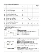
Страница 16: ...B Subtract ADD Add ON On OFF Off FBD Not allowed OPN Allow RES Reserved 3 7 LCD Setting There are three parameters to set up the UPS Refer to following diagram Parameter 1 It s for program alternative...

Страница 17: ...tput voltage in parameter 3 208 Presents output voltage is 208Vac 220 Presents output voltage is 220Vac 230 Presents output voltage is 230Vac 240 Presents output voltage is 240Vac 02 Output frequency...

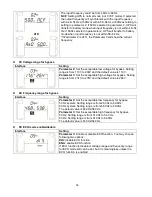
Страница 18: ...e default value is 110V Parameter 3 Set the acceptable high voltage for bypass Setting range is from 231V to 276V and the default value is 264V 04 Frequency range for bypass Interface Setting Paramete...

Страница 19: ...Hz 08 Bypass mode setting Interface Setting Parameter 2 OPN Bypass allowed When selected UPS will run at Bypass mode depending on bypass enabled disabled setting FBD Bypass not allowed When selected i...

Страница 20: ...battery 13 Battery voltage adjustment Interface Setting Parameter 2 Select Add or Sub function to adjust battery voltage to real figure Parameter 3 the voltage range is from 0V to 5 7V the default va...

Страница 21: ...output for energy saving LCD display CVCF mode Description When input frequency is within 46 to 64Hz the UPS can be set at a constant output frequency 50 Hz or 60 Hz The UPS will still charge battery...

Страница 22: ...ages in LCD panel LCD display 3 9 Fault Code Fault event Fault code Icon Fault event Fault code Icon Bus start failure 01 None Negative power fault 1A None Bus over 02 None Battery SCR short circuited...

Страница 23: ...ing twice every second Battery unconnected Beeping every second Over charge Beeping every second EPO enable Beeping every second Fan failure Over temperature Beeping every second Charger failure Beepi...

Страница 24: ...oads from UPS output first Then shut down the UPS and restart it Fault code is shown as 43 The icon lights on LCD display and alarm beeps continuously UPS is overload too long and becomes fault Then U...

Страница 25: ...required precautionary measures may replace batteries and supervise operations Unauthorized persons must be kept well away from the batteries Verify that no voltage between the battery terminals and...

Страница 26: ...2 A 10 max Charging Voltage 13 65 V 1 Long run Model Type Depending on applications Numbers 16 20 Charging Current 4 A 10 max 4 A 10 max Charging Voltage 13 65 V 1 PHYSICAL Standard Model Dimension DX...

Страница 27: ...25...

Отзывы: