9
Installation
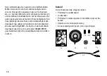
• Open the locomotive and remove the housing comple
-
tely (Figure 1).
• Mount the speaker in the location specified for it
(Figure 2), using the 4 screws and spacers.
• Remove the mode of operation switch from the
locomotive and replace it with the circuit board
included with this kit. This circuit board has a mode of
operation switch and a volume controller.
• Connect the cable to the sound circuit board (Figure 4):
– Speaker as plugged into place
– Volume controller as plugged into place
+
-
– The cable included with the kit for supplying power
to the free pair of contacts is to be connected
either to the decoder or to the locomotive circuit
board (Figure 3)
– Plug in the reed switch if necessary (
)
• Using 2 screws, mount the sound circuit board in the
lower part of the locomotive (Figure 2).
• Check all of the mounting points and electrical con
-
nections again, even those that you have not touched.
• Carefully re-assemble the locomotive. When doing
this make sure that no wires or cables are pinched.
Safety Notes
• This product may only be used with an operating
system designed for it.
• Use only switched mode power packs and transfor
-
mers made for your local power system.
• Pay attention under all circumstances to the safety
notes in the instructions for your operating system.
• Not suitable for children under the age of 15.
•
IMPORTANT!
This product has sharp edges and
points related to its function.
Important Notes
• The operating instructions and the packaging are
component parts of this product and must be pre-
served as well as passed on to other parties taking
possession of this product.
• Information about disposal in Europe (German text):
www.maerklin.com/en/imprint.html
Functions
• This product is designed for operation in the 2x52x
series and comparable LGB diesel locomotives (DC,
0 – 24 volts).
Содержание 65006
Страница 1: ...Sound Nachr stsatz 65006...
Страница 31: ...31...


