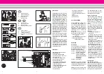
Lanterns (upper front): Pull the
lantern forward to remove it from the
smokebox. Carefully pull on the cable
to remove the light bulb from the
lantern housing. Remove and replace
the bulb. Reassemble.
Lanterns (rear): Remove the screw
holding the lantern on the body. Pull
off the lantern. Remove and replace
the bulb. Reassemble.
Cab light: Using tweezers, remove
and replace the bulb.
Replacing the smoke generator
- Turn the smoke stack and pull it
from the model (Fig. 6).
- Pull the safety cover out of the
smoke stack (Fig. 7).
- Use pliers or tweezers to pull the
old smoke generator out of the
stack.
- Cut the wires to the old generator
and attach them to the replace-
ment generator (Fig. 8).
- Insulate the connections and push
the replacement generator into the
stack.
- Reassemble.
Maintenance parts
50010 Smoke and Cleaning Fluid
50019 Maintenance Oil
51020 Gear Lubricant
62205 Motor
63120 Brushes, 14 mm, 16 mm,
8 pieces
63218 Standard Pick-Up Shoes,
2 pieces
65853 Smoke Generator, 5 V
68511 Plug-In Bulb, Clear, 5 V,
10 pieces
INSTRUCTIONS FOR ADVANCED
USERS
MTS Onboard Decoder (only 21471)
Programming functions
You can program numerous func-
tions of the onboard decoder to suit
your requirements. If you want to do
this, program the “function values”
in “registers” (CVs) using a PC and
the 55045 MTS PC Decoder
Programming Module. You can also
program the function values using a
55015 Universal Remote.
Hints:
- For normal operation, it is not nec-
essary to change the function val-
ues.
- If programming results in unsatis-
factory operation, you can repro-
gram the factory pre-set values of
most important CVs: Program reg-
ister CV55 to function value 55.
This also reprograms the loco
address to the factory pre-set
value.
To reprogram the factory pre-set
function values with the 55015,
select programming mode “P” (dis-
plays shows “P --”). Then input 6, 5,
and 5 and press the right arrow but-
ton. The display shows “P --” again:
Input 5, 5, and 5 and press the right
arrow button again.
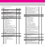
You can program the following registers:
Register Function
Available Factory
values
pre-set
CV1
Loco address
(00-22)
[3]
CV2
Starting voltage
(0-255)
[2]
voltage for speed setting 1 - if loco starts only at a higher
speed setting, increase value.
CV3
Acceleration (1 = fast, 255 = slow)
(1-255)
[3]
CV4
Braking (1 = fast, 255 = slow)
(1-255)
[3]
CV5
Max. voltage
(1-255)
[255]
Voltage for highest speed step - if a lower top speed is
desired, decrease value.
CV5
after input of CV6 (when programming with older 55015)
function value for CV to be programmed
CV6
CV to be programmed (when programming with older 55015)
CV29
NMRA configuration
[4]
Bit programming
Bit 1: direction, 0 = normal, 1 = reversed [0]
Bit 2: speed steps, 0 = 14 (LGB), 2 = 28 [0]
Bit 3: analog operation, 0 = not possible, 4 = possible [4]
Bit 4: not used [0]
Bit 5: speed steps, 0 = factory-programmed,
16 = user-programmed [0]
Bit 6: address area, 0 = 0-127 (LGB), 32 = 128-10039 [0]
To program, add the values for the individual Bits and
program the resulting function value.
Hint: To program a loco to reversed direction of travel (for
example, F7 A-B-A combination), program function value 5.
Attention! Loco addresses 128-10039 and 28 speed steps
cannot be used with LGB MTS).
CV49
Voltage for function terminal F1
(1-32)
[32]
(depends on loco model, do not change, as functions
can be affected or destroyed)
CV50
Voltage for lighting terminals (see CV49)
(1-32)
[5]
CV51
Command for function terminal F1
[13]
0 = lighting button 9
1 = button 1 (buttons 2-8 not used)
9 = button 1 (buttons 2-8 used as well)
10 = button 2
11 = button 3
12 = button 4
13 = button 5
14 = button 6
15 = button 7
16 = button 8
64 = lighting button 9 (on only when loco is reversing)
65 = button 1 (on only when loco is reversing)
128 = lighting button 9 (on only when loco is moving forward)
129 = button 1 (on only when loco is moving forward)
17
16


