3. TECHNICAL BRIEF
- 68 -
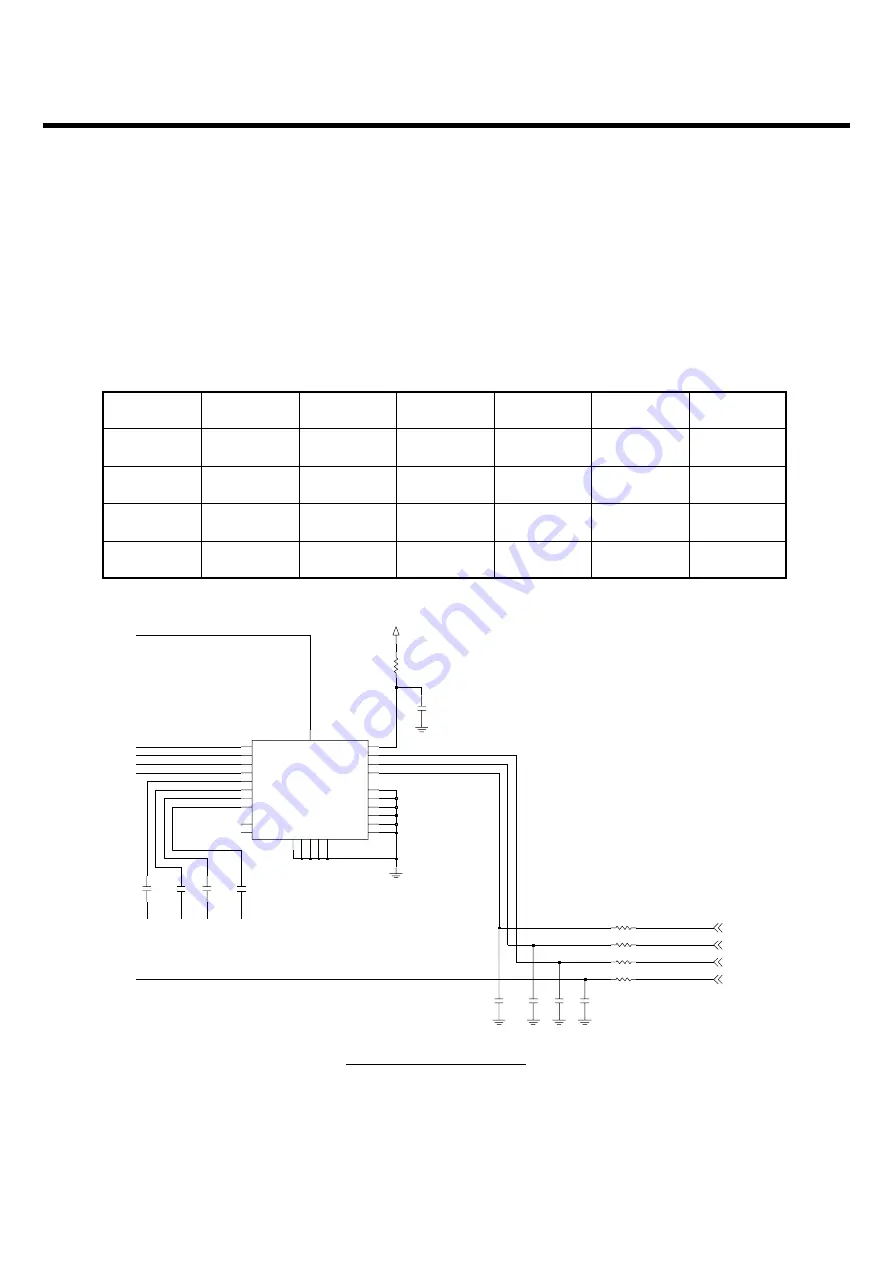
3.26. Front End Module control
Implemented in the S-Gold2 (U101) are three outputs which are VC2, VC3 and VC4 for direct control
of front end modules with three logic input pins to select RX and TX mode as well as low and high
band operation.
Table 12 FEM Control Logic
Figure 40 FEM schematic
MODE
Tx 1GHz
Tx 2GHz
Rx GSM
Rx EGSM
Rx DCS
TX PCS
VDD
ON
ON
ON
ON
ON
ON
VCTRL1
ON
ON
OFF
OFF
OFF
OFF
VCTRL2
OFF
ON
ON
ON
OFF
OFF
VCTRL3
OFF
OFF
ON
OFF
ON
OFF
GSM850
DCS
LB RF Input
Front End Module
EGSM
PCS
HB RF Input
0.1u
C405
VRF2V85
1.2p
C418
1.5p
C416
0
R403
1.5p
C417
1.2p
C419
L407
6
TX1G
8
TX2G
22
VCTRL1
VCTRL2
21
VCTRL3
20
VDD
3
EGSM_RX-
16
GMS_RX-
18
GND1
2
GND10
25
26
GND11
GND2
4
5
GND3
GND4
7
9
GND5
GND6
10
GND7
11
23
GND8
GND9
24
19
13
PCS_RX-
12
U401
YGHF-S006A
ANT
1
15
DCS_RX-
14
17
L406
C467
100p
R436
100
R438
0
100
R437
100p
C464
100
R435
100p
C465
NA
C466
VC4
VC2
VC3
VC1
Содержание Prada KE850
Страница 1: ...Date March 2007 Issue 1 0 Service Manual Model KE850 Service Manual KE850 ...
Страница 3: ... 4 ...
Страница 5: ... 6 ...
Страница 70: ...4 PCB layout 71 4 PCB layout 4 1 Main Sub PCB component placement Main PCB Top Main PCB Top placement ...
Страница 71: ...4 PCB layout 72 Main PCB bottom Main PCB bottom placement ...
Страница 115: ... 116 6 Download S W upgrade 6 Press the START button ...
Страница 116: ... 117 6 Download S W upgrade 7 Stand by condition Wait is displayed connect the Phone KE850 KE850P40 7 V09a ...
Страница 117: ...6 Download S W upgrade 118 KE850 KE850P40 7 V09a KE850 KE850P40 7 V09a ...
Страница 127: ... 128 LGMC 8 pcb layout ...
Страница 128: ... 129 LGMC 8 pcb layout ...
Страница 129: ... 130 LGMC 8 pcb layout ...
Страница 130: ... 131 LGMC 8 pcb layout ...
Страница 131: ... 132 8 pcb layout ...
Страница 132: ... 133 8 pcb layout ...
Страница 133: ... 134 8 pcb layout ...
Страница 134: ... 135 8 pcb layout ...
Страница 135: ... 136 8 pcb layout ...
Страница 136: ... 137 8 pcb layout ...
Страница 137: ... 138 ...
Страница 139: ...9 RF Calibration 140 9 2 3 Click SETTING Menu 9 2 4 Setup Ezlooks menu such as the following figure ...
Страница 141: ...9 RF Calibration 142 9 2 7 Select MODEL 9 2 8 Click START for RF calibration 9 2 9 RF Calibration finishes ...
Страница 142: ...9 RF Calibration 143 9 2 10 Calibration data will be saved to the following folder Saving format year month day PASS ...
Страница 149: ... 150 ...
Страница 151: ... 152 ...
Страница 172: ...Note ...
Страница 173: ...Note ...


