background image

Copyright ©2011 LG Electronics. Inc. All right reserved. 
Only for training and service purposes

LGE Internal Use Only

- 5 -

IC Remove/Replacement

Some  chassis  circuit  boards  have  slotted  holes  (oblong)  through
which  the  IC  leads  are  inserted  and  then  bent  flat  against  the
circuit foil. When holes are the slotted type, the following technique
should be used to remove and replace the IC. When working with
boards  using  the  familiar  round  hole,  use  the  standard  technique
as outlined in paragraphs 5 and 6 above.

Removal

1.  Desolder and straighten each IC lead in one operation by gently

prying  up  on  the  lead  with  the  soldering  iron  tip  as  the  solder
melts.

2.  Draw  away  the  melted  solder  with  an  anti-static  suction-type

solder removal device (or with solder braid) before removing the
IC.

Replacement

1.  Carefully insert the replacement IC in the circuit board.
2.  Carefully  bend  each  IC  lead  against  the  circuit  foil  pad  and

solder it.

3.  Clean the soldered areas with a small wire-bristle brush.

(It is not necessary to reapply acrylic coating to the areas).

"Small-Signal" Discrete Transistor
Removal/Replacement

1.  Remove the defective transistor by clipping its leads as close as

possible to the component body.

2.  Bend into a "U" shape the end of each of three leads remaining

on the circuit board.

3.  Bend into a "U" shape the replacement transistor leads.
4.  Connect  the  replacement  transistor  leads  to  the  corresponding

leads  extending  from  the  circuit  board  and  crimp  the  "U"  with
long  nose  pliers  to  insure  metal  to  metal  contact  then  solder
each connection.

Power Output, Transistor Device
Removal/Replacement

1.  Heat and remove all solder from around the transistor leads.
2. Remove the heat sink mounting screw (if so equipped).
3.  Carefully remove the transistor from the heat sink of the circuit

board.

4.  Insert new transistor in the circuit board.
5. Solder each transistor lead, and clip off excess lead.
6.  Replace heat sink.

Diode Removal/Replacement

1.  Remove  defective  diode  by  clipping  its  leads  as  close  as

possible to diode body.

2.  Bend  the  two  remaining  leads  perpendicular  y  to  the  circuit

board.

3.  Observing  diode  polarity,  wrap  each  lead  of  the  new  diode

around the corresponding lead on the circuit board.

4.  Securely crimp each connection and solder it.
5.

Inspect  (on  the  circuit  board  copper  side)  the  solder  joints  of

the two "original" leads. If they are not shiny, reheat them and if
necessary, apply additional solder.

Fuse and Conventional Resistor
Removal/Replacement

1.  Clip each fuse or resistor lead at top of the circuit board hollow

stake.

2.  Securely  crimp  the  leads  of  replacement  component  around

notch at stake top.

3.  Solder the connections.

CAUTION:

Maintain  original  spacing  between  the  replaced

component  and  adjacent  components  and  the  circuit  board  to
prevent excessive component temperatures.

Circuit Board Foil Repair

Excessive  heat  applied  to  the  copper  foil  of  any  printed  circuit
board  will  weaken  the  adhesive  that  bonds  the  foil  to  the  circuit
board  causing  the  foil  to  separate  from  or  "lift-off"  the  board.  The
following  guidelines  and  procedures  should  be  followed  whenever
this condition is encountered.

At IC Connections

To  repair  a  defective  copper  pattern  at  IC  connections  use  the
following  procedure  to  install  a  jumper  wire  on  the  copper  pattern
side  of  the  circuit  board.  (Use  this  technique  only  on  IC
connections).

1.  Carefully  remove  the  damaged  copper  pattern  with  a  sharp

knife. (Remove only as much copper as absolutely necessary).

2.  carefully  scratch  away  the  solder  resist  and  acrylic  coating  (if

used) from the end of the remaining copper pattern.

3.  Bend a small "U" in one end of a small gauge jumper wire and

carefully crimp it around the IC pin. Solder the IC connection.

4.  Route  the  jumper  wire  along  the  path  of  the  out-away  copper

pattern and let it overlap the previously scraped end of the good
copper  pattern.  Solder  the  overlapped  area  and  clip  off  any
excess jumper wire.

At Other Connections

Use  the  following  technique  to  repair  the  defective  copper  pattern
at  connections  other  than  IC  Pins.  This  technique  involves  the
installation  of  a  jumper  wire  on  the  component  side  of  the  circuit
board.

1.  Remove the defective copper pattern with a sharp knife.

Remove at least 1/4 inch of copper, to ensure that a hazardous
condition will not exist if the jumper wire opens.

2.  Trace  along  the  copper  pattern  from  both  sides  of  the  pattern

break  and  locate  the  nearest  component  that  is  directly
connected to the affected copper pattern.

3.  Connect  insulated  20-gauge  jumper  wire  from  the  lead  of  the

nearest component on one side of the pattern break to the lead
of the nearest component on the other side.
Carefully crimp and solder the connections.

CAUTION:

Be sure the insulated jumper wire is dressed so the

it does not touch components or sharp edges.

Содержание M2550D

Страница 1: ...IS READ THE SAFETY PRECAUTIONS IN THIS MANUAL CHASSIS LD11C MODEL M2550D M2550D PSN North Latin America http aic lgservice com Europe Africa http eic lgservice com Asia Oceania http biz lgservice com Internal Use Only P NO MFL63642153 1108 REV00 Printed in Korea ...

Страница 2: ...ll right reserved Only for training and service purposes LGE Internal Use Only 2 CONTENTS CONTENTS 2 PRECAUTIONS 3 SPECIFICATION 6 ADJUSTMENT INSTRUCTION 11 TROUBLE SHOOTING 15 BLOCK DIAGRAM 20 EXPLODED VIEW 21 SCHEMATIC CIRCUIT DIAGRAM ...

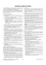
Страница 3: ...d Check Antenna Cold Check With the instrument AC plug removed from AC source connect an electrical jumper across the two AC plug prongs Place the AC switch in the on position connect one lead of ohm meter to the AC plug prongs tied together and touch other ohm meter lead in turn to each exposed metallic parts such as antenna terminals phone jacks etc If the exposed metallic part has a return path...

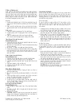
Страница 4: ... on your body by touching a known earth ground Alternatively obtain and wear a commercially available discharging wrist strap device which should be removed to prevent potential shock reasons prior to applying power to the unit under test 2 After removing an electrical assembly equipped with ES devices place the assembly on a conductive surface such as aluminum foil to prevent electrostatic charge...

Страница 5: ...the solder joints of the two original leads If they are not shiny reheat them and if necessary apply additional solder Fuse and Conventional Resistor Removal Replacement 1 Clip each fuse or resistor lead at top of the circuit board hollow stake 2 Securely crimp the leads of replacement component around notch at stake top 3 Solder the connections CAUTION Maintain original spacing between the replac...

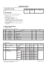
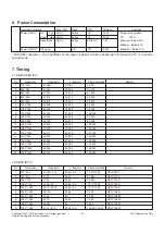
Страница 6: ...each drawing and specification by part number in accordance with BOM 2 5 The receiver must be operated for about 5 minutes prior to the adjustment 3 Module Specification 3 1 General Features Model Market Brand M2550D Brazil LG No Item Specification Unit Remark 1 Panel Size 634 4mm 25 inches 2 Panel Type TN 3 Operating Mode Normally White 4 Backlight Unit White LED 5 Max Resolution 1920 x 1080 6 Pi...

Страница 7: ...ment Temp 10 C 35 C Humidity 20 80 5 Storage Environment Temp 10 C 60 C non condensing Humidity 5 90 non condensing No Item Specification Remarks 1 Market Brazil 2 Receiving System 1 SBTVD PAL M PAL N 3 Available Channel 1 VHF 02 13 2 UHF 14 69 3 DTV 07 69 4 CATV 01 135 4 Component Input 1EA Y Cb Cr Y Pb Pr 5 RGB Input RGB PC Analog D SUB 15Pin 6 HDMI Input 2EA HDMI Rear HDMI version 1 3 support P...

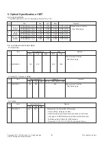
Страница 8: ...1 Color coordinate The W B Tolerance is 0 01 for Adjustment but for DQA 0 03 5 2 Luminance and Contrast Ratio PC Mode RGB No Item Luminance cd m2 C R Remark Min Typ Max Min Typ Measurement Condition After 30min aging 1 M23 2550D 180 200 800 1000 AV Mode RF Component HDMI No Item Luminance cd m2 C R min Remark Min Typ Max RF AV COMPONENT HDMI 1 M23 2550D 180 200 800 Measurement Condition After 30mi...

Страница 9: ...0 1080 67 500 60 000 148 500 No Resolution H freq kHz V freq Hz Pixel clock MHz Remark 1 720 480 31 469 31 5 59 94 60 27 00 27 03 SDTV 480P 2 720 576 31 25 50 00 27 864 SDTV 576P 3 1280 720 37 50 50 00 74 250 HDTV 720P 4 1280 720 44 96 45 59 94 60 74 17 74 25 HDTV 720P 5 1920 1080 33 72 33 75 59 94 60 74 17 74 25 HDTV 1080I 6 1920 1080 28 125 50 00 74 25 HDTV 1080I 7 1920 1080 27 00 24 74 25 HDTV ...

Страница 10: ... 625I 50Hz 4 720 480 31 47 59 94 27 000 SDTV 480P 5 720 480 31 50 60 00 27 027 SDTV 480P 6 720 576 31 25 50 00 27 000 SDTV 576P 50Hz 7 1280 720 44 96 59 94 74 176 HDTV 720P 8 1280 720 45 00 60 00 74 250 HDTV 720P 9 1280 720 37 50 50 00 74 25 HDTV 720P 50Hz 10 1920 1080 33 72 59 94 74 176 HDTV 1080I 11 1920 1080 33 75 60 00 74 250 HDTV 1080I 12 1920 1080 28 125 50 00 74 250 HDTV 1080I 50Hz 13 1920 ...

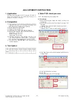
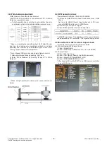
Страница 11: ...tage 220V 60Hz 2 6 Adjustment equipment Color Analyzer CA 210 or CA 110 Pattern Generator MSPG 925L or Equivalent DDC Adjustment Jig equipment SVC remote controller 2 7 Don t push The IN STOP KEY after completing the function inspection 3 Tool Option 4 Main PCB check process APC After Manual Insult executing APC 4 1 Download 1 Execute ISP program Mstar ISP Utility and then click Config tab 2 Set a...

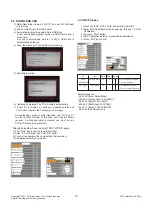
Страница 12: ...fter downloading have to adjust TOOL OPTION again 1 Push ADJ key in service remote controller 2 Select 1 Tool Option and Push OK button 3 Punch in the number Each model has their number 4 Completed selecting Tool option 4 3 ADC Process 1 Press the ADJ KEY on R C and enter EZ ADJUST 2 Enter ADC Calibration mode by pushing G key at 6 ADC Calibration 3 Push the Start button 4 ADC Calibration External...

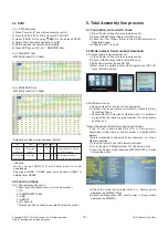
Страница 13: ...C is ok 00 5 2 Model name Serial number Download 5 2 1 Model name Serial number D L 1 Press Power on key of service remote control 2 Connect RS232 Signal Cable to RS 232 Jack 3 Write Serial number by use RS 232 4 Must check the serial number at the Diagnostics of SET UP menu Refer to below 5 2 2 Method notice a Serial number D L is using of scan equipment b Setting of scan equipment operated by Ma...

Страница 14: ... by pushing G key at 6 White Balance When doing Adjustment Please make circumstance as below 5 4 DPM operating check Measurement Condition 100 240V 50 60Hz 1 Set Input to RGB PC and connect D sub cable to set RGB Mode Set Input to HDMI1 2 with Input Label set to PC and connect HDMI1 2 cable to set HDMI Mode 2 Cut off H sync or V sync of signal 3 Check DPM operation refer to the below table LED SET...

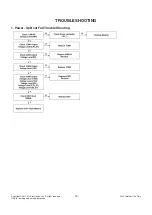
Страница 15: ...Copyright 2011 LG Electronics Inc All right reserved Only for training and service purposes LGE Internal Use Only 15 TROUBLESHOOTING 1 Power Up Boot Fail Trouble Shooting ...

Страница 16: ...Copyright 2011 LG Electronics Inc All right reserved Only for training and service purposes LGE Internal Use Only 16 2 No Picture Trouble Shooting ...

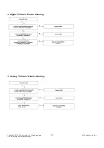
Страница 17: ...Copyright 2011 LG Electronics Inc All right reserved Only for training and service purposes LGE Internal Use Only 17 4 Analog TV Video Trouble Shooting 3 Digital TV Video Trouble Shooting ...

Страница 18: ...Copyright 2011 LG Electronics Inc All right reserved Only for training and service purposes LGE Internal Use Only 18 5 Component Video Trouble Shooting 6 RGB Video Trouble Shooting ...

Страница 19: ... 19 Copyright 2011 LG Electronics Inc All right reserved Only for training and service purposes LGE Internal Use Only 7 HDMI Video Trouble Shooting 8 All Source Audio Trouble Shooting ...

Страница 20: ...Copyright 2011 LG Electronics Inc All right reserved Only for training and service purposes LGE Internal Use Only 20 BLOCK DIAGRAM ...

Страница 21: ...l and mechanical parts in this chassis have special safety related characteristics These parts are identified by in the Schematic Diagram and EXPLODED VIEW It is essential that these special safety parts should be replaced with the same components as recommended in this manual to prevent X RADIATION Shock Fire or other Hazards Do not modify the original design without permission of manufacturer IM...

Страница 22: ...PDF created with pdfFactory trial version www pdffactory com Copyright ⓒ 2011 LG Electronics Inc All right reserved Only for training and service purposes LGE Internal Use Only ...

Страница 23: ...PDF created with pdfFactory trial version www pdffactory com Copyright ⓒ 2011 LG Electronics Inc All right reserved Only for training and service purposes LGE Internal Use Only ...

Страница 24: ...PDF created with pdfFactory trial version www pdffactory com Copyright ⓒ 2011 LG Electronics Inc All right reserved Only for training and service purposes LGE Internal Use Only ...

Страница 25: ...PDF created with pdfFactory trial version www pdffactory com Copyright ⓒ 2011 LG Electronics Inc All right reserved Only for training and service purposes LGE Internal Use Only ...

Страница 26: ...PDF created with pdfFactory trial version www pdffactory com Copyright ⓒ 2011 LG Electronics Inc All right reserved Only for training and service purposes LGE Internal Use Only ...

Страница 27: ...PDF created with pdfFactory trial version www pdffactory com Copyright ⓒ 2011 LG Electronics Inc All right reserved Only for training and service purposes LGE Internal Use Only ...

Страница 28: ...PDF created with pdfFactory trial version www pdffactory com Copyright ⓒ 2011 LG Electronics Inc All right reserved Only for training and service purposes LGE Internal Use Only ...

Страница 29: ...PDF created with pdfFactory trial version www pdffactory com Copyright ⓒ 2011 LG Electronics Inc All right reserved Only for training and service purposes LGE Internal Use Only ...

Страница 30: ...PDF created with pdfFactory trial version www pdffactory com Copyright ⓒ 2011 LG Electronics Inc All right reserved Only for training and service purposes LGE Internal Use Only ...

Страница 31: ......

Отзывы: