-3-21-
COMPONENT ACCESS
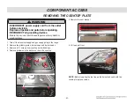
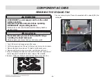
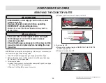
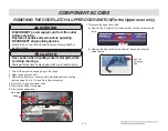
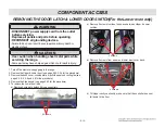
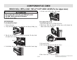
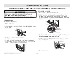
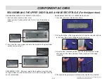
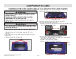
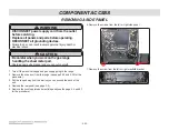
1. Turn off the electrical supply and gas supply going to the range.
2. Pull the range away from the wall so that you can access the rear panel.
3. Remove the rear back cover and motor cover (see step 4~5 on page 3-2)
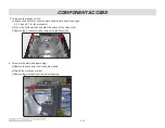
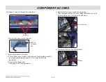
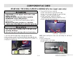
4. Disconnect the wires from the latch drive motor and switch.
5. Remove the 1 screw from the latch drive.
6. Unhook the Latch rod from the cam.
• DISCONNECT power supply cord from the outlet
before servicing.
• Replace all panels and parts before operating.
• RECONNECT all grounding devices.
- Failure to do so can result in severe personal injury, death or
electrical shock.
WARNING
• Use caution when handling sheet metal parts while
servicing the range.
- Some parts may have sharp edges, which could result in injury.
CAUTION
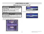
REMOVING THE DOOR LOCK ASSEMBLY (FOR THE LOWER OVEN ONLY)
1 screws
Содержание LUTG4519SN
Страница 63: ... 6 1 COMPOSITION OF CONTROL Wiring Diagram ...
Страница 66: ... 6 4 COMPOSITION OF CONTROL P N EBR80595412 Oven Relay PCB CN53 CN51 CN52 ...
Страница 67: ... 6 5 COMPOSITION OF CONTROL SMPS PCB Touch PCB P N EBR80595701 P N EBR82864102 CN02 CN01 CN1 ...
Страница 99: ...UPPER DOOR PARTS EV 1021 1009 170R 1035 1035 170L 1015 1020 173U 173U 1008 102S 102S 102L W243 1000 W222 1801 ...
Страница 100: ...LOWER DOOR PARTS EV 1041 1009 1115 1120 102L 1018 173L 102U W243 W222 W222 1100 1704 1704 102L 173L 102U W101 W101 1801 ...
Страница 105: ......

