
28
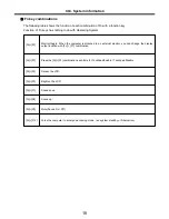
BIOS Setup
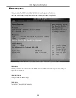
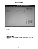
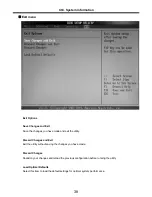
BIOS (Basic Input and Output System) Setup
saves the system configuration in
CMOS RAM
, and
check the configurations during startup. Use the
BIOS Setup Utility
to change and save the system
environment, hardware configurations, power saving mode, etc.
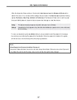
· Open the BIOS Setup Utility in the following situations :
1. to change the BIOS setup
2. to replace the backup battery
3. system configuration error occurs
4. to change the boot order
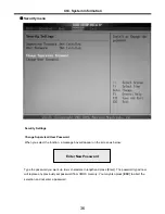
5. to set/change a password
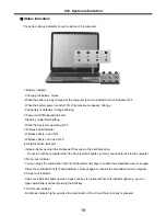
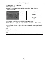
Press the power button.
When the
LG
logo appears on the screen, press and enter the
BIOS Setup Utility
.
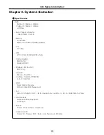
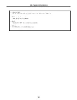
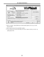
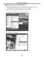
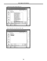
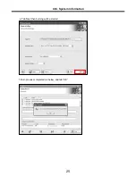
Ch3. System information
Содержание K1
Страница 1: ...0 Service Manual K1 LG Electronics ...
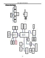
Страница 18: ...17 System Block Diagram Ch3 System information ...
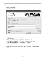
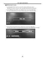
Страница 25: ...24 Ch3 System information c Select File Format as Image Files iso d Open Image File iso which is sent from LGE ...
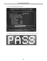
Страница 26: ...25 Ch3 System information e Tab Next then burning will be started f Burn process completed as below and tab OK ...
Страница 58: ...57 3 Remove HDD using a tag Ch5 Removing and replacing a part ...
Страница 59: ...58 Ch5 Removing and replacing a part ...
Страница 61: ...60 3 Remove the Memory Ch5 Removing and replacing a part ...
Страница 64: ...63 2 Disconnect the Fan Assembly connector 3 Remove the Fan Assembly Ch5 Removing and replacing a part ...
Страница 67: ...66 Ch5 Removing and replacing a part ...
Страница 69: ...68 3 Disconnect the Connector 4 Remove the Retainer Ch5 Removing and replacing a part ...
Страница 71: ...70 3 Disconnect the Keyboard Connector then remove the Keyboard Ch5 Removing and replacing a part ...
Страница 73: ...72 2 Disconnect the LVDS Inverter Cable Ch5 Removing and replacing a part ...
Страница 74: ...73 3 Remove the Display Module Ch5 Removing and replacing a part ...
Страница 77: ...76 4 Remove the Keydeck 5 Disconnect the Touchpad Connector Ch5 Removing and replacing a part ...
Страница 78: ...77 6 Disconnect the Power Cable then remove the Keydeck Ch5 Removing and replacing a part ...
Страница 80: ...79 2 Remove the Main Board 3 Disconnect the DC In LAN USB Cable Ch5 Removing and replacing a part ...
Страница 81: ...80 4 Disconnect the MDC Cable Ch5 Removing and replacing a part ...
Страница 83: ...82 7 Remove the USB Board Ch5 Removing and replacing a part ...
Страница 90: ...K1 Buffalo EXPLODED VIEW 2 NHDDB NCVRH NSCRF NSCRF NSCRF NSCRF NBRKB ...


