


-153-
12.4 RF TX Check :
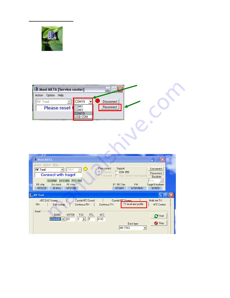
(1) Open “ Meta_RF_Tool ”.
(2) Pull in UART cable.
(3) Inset RF-Cable (AG8960).
(4) Select proper com port and press “Reconnect” and then press handset’s power key.
(5) Loading database Make sure the same to handset.
(6) AG8960 need to set TCH Parms.
(7)Press “TX level and profile” to TX Test.
Step2
Step1
Содержание GB175
Страница 1: ...1 GB175 Service Manual LG Electronics ...
Страница 16: ... 16 3 TECHNICAL BRIEF 3 1 Digital Main Processor Figure 3 1 1 MT6225 FUNCTIONAL BLOCK DIAGRAM ...
Страница 22: ... 22 Figure 3 1 2 MT6225 BLOCK DIAGRAM ...
Страница 28: ... 28 3 5 Memory Module PF38F4050M0Y0CG Figure 3 5 1 PF38F4050M0Y0CG FUNCTIONAL BLOCK DIAGRAM ...
Страница 30: ... 30 ...
Страница 31: ... 31 ...
Страница 33: ... 33 ...
Страница 36: ... 36 Figure 3 9 2 IM152FBN5A Block Diagram ...
Страница 40: ... 40 3 12 Audio Interface Figure 3 12 1 Main Speaker Interface Figure 3 12 2 Main Microphone Recevice Interface ...
Страница 45: ... 45 4 2 SIM Card Trouble 4 2 1 Test Point 4 2 2 Circuit Diagram VSIM VSIM ...
Страница 48: ... 48 4 4 Keypad Trouble 4 4 1 Test Point 4 4 2 Circuit Diagram Key pad Top View ...
Страница 49: ... 49 4 4 3 Checking Flow Change Metal Dome Start Change PCB NG OK Check Metal Dome ...
Страница 50: ... 50 4 5 RTC Trouble 4 5 1 Test Point 4 5 2 Circuit Diagram XIN XOUT VRTC XIN XOUT ...
Страница 51: ... 51 XIN XOUT ...
Страница 53: ... 53 4 6 Key Backlight Trouble ...
Страница 54: ... 54 4 6 1 Test Point 4 6 2 Circuit Diagram TP8 TP8 TP9 TP9 ...
Страница 56: ... 56 4 7 LCM Backlight Trouble 4 7 1 Test Point TP11 TP10 TP12 ...
Страница 58: ... 58 4 8 LCM Trouble 4 8 1 Test Point 4 8 2 Circuit Diagram TP13 TP14 TP14 TP13 ...
Страница 60: ... 60 4 9 Microphone Trouble 4 9 1 Test Point 4 9 2 Circuit Diagram TP15 TP15 ...
Страница 62: ... 62 4 10 Receiver Trouble 4 10 1 Test Point 4 10 2 Circuit Diagram TP16 TP17 TP16 TP17 ...
Страница 66: ... 66 4 12 Headphone Trouble 4 12 1 Test Point 4 12 2 Circuit Diagram TP28 TP29 TP30 TP30 TP28 TP29 ...
Страница 69: ... 69 4 13 Charging Trouble 4 13 1 Test Point 4 13 2 Circuit Diagram TP31 TP31 ...
Страница 73: ... 73 4 15 TRX PAM 4 15 1 Test Point TP38 TP37 TP34 TP35 TP39 TP36 TP40 ...
Страница 74: ... 74 4 15 2 Circuit Diagram TP34 TP35 TP36 TP37 TP41 TP40 TP39 ...
Страница 78: ... 78 5 DOWNLOAD 5 1 Download setup ...
Страница 81: ... 81 5 You can see the below Installing picture and then click the Close button installation complete ...
Страница 87: ... 87 6 BLOCK DIAGRAM ...
Страница 88: ... 88 7 CIRCUIT DIAGRMA ...
Страница 89: ... 89 ...
Страница 90: ... 90 ...
Страница 91: ... 91 ...
Страница 92: ... 92 ...
Страница 93: ... 93 ...
Страница 94: ... 94 ...
Страница 95: ... 95 ...
Страница 96: ... 96 8 BGA IC PIN Check 8 1 BGA PIN Check of main chip MT6225 BB_MT6225 U100 BGA use BGA non us ...
Страница 97: ... 97 8 2 BGA PIN Check of Memory PF38F4050M0Y0CG PF38F4050M0Y0CG U200 BGA use BGA non use ...
Страница 98: ... 98 8 3 BGA PIN Check of PMIC MT6318 MT6318 U502 BGA use BGA non use ...
Страница 99: ... 99 9 PCB LAYOUT TOP J401 Receiver PAD No receiver ...
Страница 103: ... 103 Work Flow ...
Страница 105: ... 105 11 CALIBRATION 11 1 Test Equipment set up ...
Страница 109: ... 109 ...
Страница 111: ... 111 Execute Measurement Automation to check equipment address Choose Devices and Interfaces ...
Страница 113: ... 113 Setup your CMU Base GPIB address and power supply address ...
Страница 114: ... 114 ATE Tool system setting Execute MTK _ ate demo Press Report System button ...
Страница 115: ... 115 Setting your equipment Setting your power supply type Choose your Power Supply Type ...
Страница 119: ... 119 How to setup your test report location Choose my computer Choose C disk ...
Страница 120: ... 120 Choose program files Choose Program Files ATE Tools KP199_KP320_KM330_KM335_KC530 file ...
Страница 121: ... 121 Setup new file and leave the window Execute MTK _ ate demo ...
Страница 122: ... 122 Press Report System button Press select test report location ...
Страница 123: ... 123 Choose your setup report Press Done ...
Страница 124: ... 124 Setup finish When you finish the setup then you press save change icon ...
Страница 125: ... 125 Press Configuration choose Cal Setting Setting your cable loss ...
Страница 126: ... 126 Press Done to save Press Configuration choose Final setting ...
Страница 128: ... 128 If you want calibration you can press initial calibration Press Calibration Test ...
Страница 129: ... 129 Key in your phone bar Code Press your phone of power on key and Start calibration ...
Страница 130: ... 130 Calibration is ok and will show PASS You can see the test report ...
Страница 131: ... 131 If you want final test you can press initial final test ...
Страница 132: ... 132 Press RF Final test ...
Страница 133: ... 133 1 Handset to insert SIM card 2 Key in bar code or IMEI number 3 power on handset ...
Страница 134: ... 134 ATE start final test ...
Страница 135: ... 135 If ATE test finish ATE will show pass ...
Страница 136: ... 136 You can see the test report ...
Страница 137: ... 137 If you want initial cal and final test you can press initial cal and final test ...
Страница 138: ... 138 Press Cal Final ...
Страница 139: ... 139 1 Handset to insert SIM card 2 Key in bar code or IMEI number 3 Power on handset ...
Страница 140: ... 140 Start calibration ...
Страница 141: ... 141 Calibration finish and power on handset again ...
Страница 142: ... 142 Start final test ...
Страница 143: ... 143 Finish Cal Final test ...
Страница 144: ... 144 Ate show the test report ...
Страница 147: ... 147 4 Install Process press Next 5 Install Process press Next 6 Install Process ...
Страница 148: ... 148 7 Install Process press Finish ...
Страница 155: ... 155 13 EXPLODED VIEW REPLACEMENT PART LIST 13 1 Exploded view ...
Страница 156: ... 156 Ass y exploded view ...