30
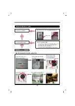
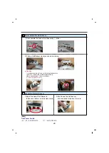
Disassemble the Hall Sensor
1) Disassemble the hook of Hall Sensor by (-) driver.
2) Pull up Hall Sensor slowly as shown in picture.
1) Adjust the hole of Hall Sensor to
the hooks of stator as picture.(red circled)
2) Push down the Hall sensor,
and assemble to the hook for sure.
Caution
If you disassemble by force,not following the directions,
the hooks of stator(red circled) might broke up.
Hence need change of stator assembly.
So disassemble cautiously.
1
Assemble the Hall Sensor
2
[Note]
Hall Sensor Part No.
• 24” / 25” : 6501KW2001A
• 27” : 6501KW2002A
Содержание F14030RD
Страница 2: ...51 P No MFL30574776 ...
Страница 15: ...14 6 WIRING DIAGRAM PCB LAYOUT PROGRAM CHART ...
Страница 17: ...16 PCB Layout Power Common Power Cord Noise Filter DRY Wash DRY Resistance 24 5 28 5 Ω Only For Dry Combo Wash ...
Страница 18: ...17 Program Chart ...
Страница 51: ...50 10 4 THE EXPLODED VIEW OF DRYER M130 M120 M230 M140 M215 M210 M216 M100 M240 M101 M220 M111 M110 ...


