background image

- 12 -

AS mark


  LG TV

Owner’s Manual

1.5V

1.5V

Alkaline batteries

Power Cord

1

2

3

4

5

6

7

8

9

0

DVD

STB

AUDIO

MODE

POWER

MUTE

TV/AV

MULTIM

EDIA

ARC

SSM

Q.VIEW

PSM

FAVOURITE

MENU

PIP PR-

REVEAL

LIST

PLAY

REW

FF

SKIP

PAUSE

STOP

RECORD

SPLIT ZOOM

SLEEP

I/II

WIN.SIZE WIN.POSITION

PIP INPUT

PIP PR+

SWAP

OK

PIP/DW

EXIT

PR

VOL

CABLE

VCR

?

TV

TEXT/

Remote Control handset

-

Optional extras can be changed or modified for quality improvement without any notification new optional extras can be
added.

-

Contract your dealer for buying these items.

Optional Extras

Accessories

Accessories

Video cables

Audio cables

6-RING SPACER

(Only DT-60PY10 series)

2-TV bracket bolts

(or DT-50PY10 series: 4-TV

bracket bolts)

(Only DT-60PY10 series : 6-Wall

mounting bracket bolts)

Ceiling mounting bracket

Wall mounting bracket

(Only DT-60PY10 series)

Tilt wall mounting bracket

(Only DT-60PY10 series)

Tilt wall mounting bracket

40

42

50

40

42

50

Ceiling mounting bracket

4

0

4

2

5

0

42

40

2-TV brackets

2-Wall brackets (option)

- Secure the TV assembly by joinning it to a wall by using the TV/Wall brackets.

Joinning the TV assembly to the wall to protect the set tumbling

• After the set must be mounted on s desk top, install the TV brackets on the TV as shown.

Insert the 2 bolts and tighten securely, in the holes on the bracket. 
(Only DT-50PY10 series: After removing the existing bolts, insert the 4 bolts and tighten secure-
ly, in the holes on the bracket.)
Install the wall brackets on the wall with 4 bolts, (not supplied with the product), as shown.
Match the height of the TV brackets and the wall brackets. 
Check to be sure the brackets are tightened securely.

• Secure the TV assembly to the wall with strong strings or wound wire cables, (not supplied

with the product), as shown.

Содержание DT-60PY10

Страница 1: ...A TV SERVICE MANUAL CAUTION BEFORE SERVICING THE CHASSIS READ THE SAFETY PRECAUTIONS IN THIS MANUAL CHASSIS AF 046A MODEL DT 60PY10 website http biz LGservice com e mail http www LGEservice com techsup html ...

Страница 2: ...NS 3 DESCRIPTION OF CONTROLS 4 SPECIFICATIONS 13 ADJUSTMENT INSTRUCTIONS 14 TROUBLE SHOOTING GUIDE 17 BLOCK DIAGRAM 31 EXPLODED VIEW 32 EXPLODED VIEW PARTS LIST 33 REPLACEMENT PARTS LIST 34 SCHEMATIC DIAGRAM PRINTED CIRCUIT BOARD ...

Страница 3: ... With the instrument AC plug removed from AC source connect an electrical jumper across the two AC plug prongs Place the AC switch in the on position connect one lead of ohm meter to the AC plug prongs tied together and touch other ohm meter lead in turn to each exposed metallic parts such as antenna terminals phone jacks etc If the exposed metallic part has a return path to the chassis the measur...

Страница 4: ...ure format TEXT These buttons are used for teletext For further details see the Teletext section switches the subtitle on or off in Digital mode Note In teletext mode the PIP PR SWAP and PIP INPUT buttons are used for teletext function VOL Volume Up Down increases decreases sound level PR Programme Up Down selects a programme switches the set on from standby FAVOURITE selects a favourite programme...

Страница 5: ...item switches the set on from standby MENU displays on screen menus one by one exits the current menu memorizes menu changes D D E E Programme Up Down selects a programme or a menu item switches the set on from standby F F G G Volume Up Down adjusts the volume adjusts menu settings Power Standby Indicator Illuminates red in standby mode Illuminates green when the set is turned on ...

Страница 6: ...e strongly recom mend that you use the cable that has a core or the EMI Filter core along with separate cable 5 COMPONENT INPUT Connect DVD video outputs to Y PB PR of COMPONENT INPUT and audio outputs to Audio sockets of AUDIO INPUT 6 AUDIO VIDEO IN SOCKETS A V INPUT 1 Connect the audio video out sockets of external equipment to these sockets S VIDEO AUDIO IN SOCKETS Connect the S VIDEO out socke...

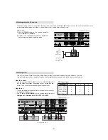
Страница 7: ...To avoid picture noise interference leave an adequate distance between the VCR and the set Watching TV programmes Turn the set on and select the programme you want Watching VCR 1 Use the TV AV button on the remote control to select VIDEO 1 or VIDEO 2 If both S VIDEO and VIDEO sockets have been connected to the S VHS VCR simultaneously only the S VIDEO can be received 2 Insert a video tape into the...

Страница 8: ...PB PR INPUT jacks on the set and connect the DVD audio outputs to the AUDIO INPUT jacks on the set as shown in the figure 2 If your DVD only has an S Video output jack connect this to the S VIDEO input on the set and connect the DVD audio outputs to the AUDIO INPUT jacks on the set as shown in the figure Note a If your DVD player does not have component video output use S Video b Digital Audio wil...

Страница 9: ...box con nector Then make the corresponding audio connections How to use 1 Turn on the digital set top box Refer to the owner s manual for the digital set top box 2 Use TV AV or MULTIMEDIA on the remote control to select Component 1 Component 2 RGB DTV or DVI DTV This set can receive Digital Over the air Cable signals without an external digital set top box However if you do receive Digital signals...

Страница 10: ...htness in PC mode If noise is present change the PC mode to another resolution change the refresh rate to another rate or adjust the bright ness and contrast on the menu until the picture is clear If the refresh rate of the PC graphic card can not be changed change the PC graphic card or consult the manufacturer of the PC graphic card Note a Depending on the graphics card DOS mode may not work if ...

Страница 11: ...stereo system via the Digital Audio Output Optical port Caution Do not look into the optical output port Looking at the laser beam may damage your vision Digital Audio Output How to connect 1 Connect one end of an optical cable to the TV Digital Audio Optical Output port 2 Connect the other end of the optical cable to the digital audio optical input on the audio equipment 3 Set the TV Speaker opti...

Страница 12: ...acket Wall mounting bracket Only DT 60PY10 series Tilt wall mounting bracket Only DT 60PY10 series Tilt wall mounting bracket 40 42 50 40 42 50 Ceiling mounting bracket 40 42 50 42 40 2 TV brackets 2 Wall brackets option Secure the TV assembly by joinning it to a wall by using the TV Wall brackets Joinning the TV assembly to the wall to protect the set tumbling After the set must be mounted on s d...

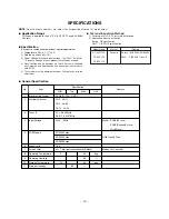
Страница 13: ...N Typ Max Unit No Item Remark V Application Range This spec is applied to the 42 50 60 PDP TV used AF 046A Chassis V Specification Each part is tested as below without special appointment 1 Temperature 25 5 C 77 9 F 2 Relative Humidity 65 10 3 Power Voltage Standard Input voltage 100 240V 50 60Hz Standard Voltage of each product is marked by models 4 Specification and performance of each parts are...

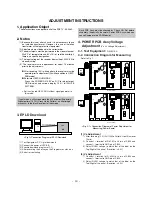
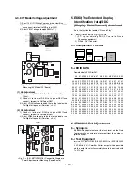
Страница 14: ...ogrammer click icon 5 End after confirming 4 POWER PCB Assy Voltage Adjustment Va Vs Voltage Adjustment 4 1 Test Equipment D M M 1EA 4 2 Connection Diagram for Measuring Refer to Fig 1 1 Va Adjustment 1 After receiving 100 Full White Pattern Heat Run over 10min 2 Connect terminal of D M M to Va pin of P805 and connect terminal to GND pin of P805 3 Adjust RV601 voltage to match that of the label on...

Страница 15: ...log digital converter 6 2 Test Equipment Service R C 801GF 802B 802F 802R or MSPG3240A Pattern Generator 720P 60Hz 100 Color Bar Pattern output will be possible and the output level will accurately have to be revised with 0 7 0 1Vp p 15 D M M P8011 VR8501 Vs ADJ VR8401 Va ADJ Fig 2 2 Connection Diagram of Power Adjustment for Measuring 60 Model PFC Board Fig 2 3 P N 6871VPMA78A Connection Diagram ...

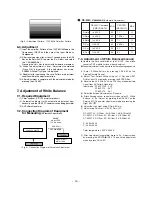
Страница 16: ...e following sequence 1 Enter 3 White Pattern by pressing ADJ KEY on the Service Remote Control 2 Select Test Pattern White using Vol Key and HEAT RUN at least 15 minutes by pressing the ENTER Key 3 Receive the AV 50Hz Full size 216 Gray window pattern signal from AV Pattern Generator Input mode DT 42PY10X AV2 DT 50PY10 AV1 DT 60PY10 AV1 4 Select the Screen Adjustment as Dynamic 5 After attaching s...

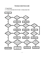
Страница 17: ...signal Doesn t the high tension output come out Doesn t the VSC signal Vs ON come out Yes Yes High tension output voltage Drop it occurs When remove the Y B D Module Input Connector output voltage Drop it occurs When remove the Y Z B D Module Input Connector Power Board high tension output voltage Drop it occurs Yes No No 9 Check the Power Board Output high tension circuit Yes 10 Check the Z B D M...

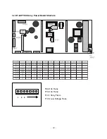
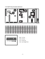
Страница 18: ... 18 1 2 DT 42PY10X Sony Power Board Structure 1 2 3 T502 Vs Trans T702 Va Trans T101 St by Trans T103 Low Voltage Trans ...

Страница 19: ... 19 1 3 DT 50PY10 Sony Power Board Structure 1 2 3 T502 Vs Trans T702 Va Trans T101 St by Trans T103 Low Voltage Trans ...

Страница 20: ... 20 1 3 DT 50PY10 Sanken Power Board Structure 1 2 3 T221 Vs Trans T271 Va Trans T121 St by Trans T201 Low Voltage Trans ...

Страница 21: ... 21 1 4 DT 60PY10 Power Board Structure 1 2 3 AC IN ...

Страница 22: ... 22 1 2 3 PFC ...

Страница 23: ... 23 1 2 3 DC DC ...

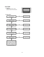
Страница 24: ...Power Switch and Power Board Cable Connect the Cable Yes No Is normal the Fuse F101 on Power Board Replace the Fuse Yes No Is connected the Power Board and 7P of VSC Board Cable Connect the Cable Yes No Is connected the Power Switch and Power Board Cable After remove the cable connection to Power Board except the CN101 connection cable authorizes the AC voltage marking on manual When ST BY 5V does...

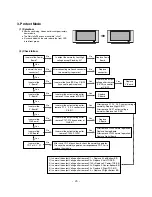
Страница 25: ... B D Yes No Is normal the X Board Is normal the output voltage after remove P1 2 3 4 5 connector of X B D After remove P1 P2 P3 P4 output voltage normality Replace Right X B D After remove P6 P7 output voltage normality Replace Left X B D Yes No Yes Is normal the VSC Board Is normal the output voltage after remove P1000 P1200 After crisis COF of each board check the normality operates If in case t...

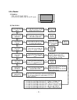
Страница 26: ... the output voltage after remove P1 2 3 4 5 connector of X B D After remove P1 P2 P3 P4 output voltage normality Replace Right X B D After remove P6 P7 output voltage normality Replace Left X B D Yes No Yes Is normal the VSC Board Is normal the output voltage after remove P1000 P1200 After crisis COF of each board check the normality operates If in case normality operates correspondence COF Fail i...

Страница 27: ...rmal the LVDS cable Is normal the VSC Digital Board Is connected the LVDS cable correctly Connect the cable correctly Yes No No Yes Operates the Thine IC IC1401 Replace Thine IC IC1401 No Is normal the Ctrl Board of Module Replace Ctrl B D No No Operates the IEP IC1301 Replace the IEP IC1301 Yes No Operates the Scaler IC701 Replace the Scaler IC700 Yes Replace the cable Yes Replace the VSC Digital...

Страница 28: ... AV mode 28 Is normal the Tuner Is normal the CXA2069Q IC301 Is connected the Tuner Cable correctly Connect the Cable correctly Yes No No Yes Is normal the VPC3230 or VPX3226 Replace the Tuner No Is normal the Input voltage IIC Communication and CVBS output Yes Is normal the Input voltage IIC Communication and HV sync No Replace the IC No Is normal the Input voltage IIC Communication and HV sync N...

Страница 29: ...o Yes Is normal the Scaler Is normal the Input voltage IIC Communication and HV sync No Replace the IC No Is normal the Sil169 IC601 Yes Is normal the Input voltage IIC Communication and HV sync No Replace the IC No Is normal the Scaler Is normal the Input voltage IIC Communication and HV sync No Replace the IC No Is correct the EDID Yes Is the latest version the Graphic card driver of the PC Inpu...

Страница 30: ...he SPK Yes Yes Is normal the RF Digital sound Is normal the MSP4410K IC501 No No Is normal the NSP6241 IC502 Yes Is normal the TAS5122 IC503 Is normal the Scaler IC503 Replace VSC Digital B D Yes Yes Yes Yes Is normal the RF Analog AV Component L R sound Is normal the CS5330A IC1205 MC33078 IC1206 Scaler IC701 Yes Is connected the Flat cable correctly Connect the Cable correctly No Yes No Replace ...

Страница 31: ... 31 BLOCK DIAGRAM BLOCK DIAGRAM ...

Страница 32: ...W 551 550 305 300 302 311 301 301 314 314 308 310 313 312 309 307 303 101 102 304 306 570 540 501 660 560 541 211 210 203 204 205 200 580 206 209 212 400 401 121 120 600 640 610 630 620 650 208 202 201 520 430 530 561 ...

Страница 33: ...FRAME FRONT SIDE AL DU 60PY10 RIGHT WITH SPK 310 3210V00256A FRAME FRONT SIDE AL DU 60PY10 LEFT WITH SPK 311 3210V00253A FRAME FRONT UPPER AL DU 60PY10 312 3790V00745L WINDOW DECO DT 60PY10 ACRYL RIGHT 313 3790V00745M WINDOW DECO DT 60PY10 ACRYL LEFT 314 4972V00113B FIXER FRAME EGI DU 60PY10 RIGHT PRESS 315 3210V00254C FRAME BOTTOM AL RZ 60PY10 NON 400 3809V00460H BACK COVER ASSEMBLY DT 60PY10 411...

Страница 34: ...G 0ISH851000A 0ILI817000G 0ILI817000G 0ILI817000G 0TR387500AA 0TR387500AA 0TR150400BA 0TR387500AA K4S641632H TL75 54P TSOP K4S641632H TL75 54P TSOP K4S641632H TL75 54P TSOP COPY M37272EFSP6 OTP 42SDIP FA5502M TE1 FUJI ELECTRIC 16P SOP KIA7042AF SOT 89 TP 4 2V VOLTAGE AT24C16AN 10SI 2 7 ATMEL 8P SOIC 1R2113S 16SOP R TP H BRIDGE DRIVER BA10339FV E2 SSOP B14PIN R TP PQ12DZ1U 5 SMD R TP REGULATOR UC38...

Страница 35: ... Q8105 Q8105 Q8106 Q8107 Q8108 Q8108 Q8201 Q8203 Q8204 Q8205 Q8206 Q8207 Q8208 Q8209 Q8212 Q8215 Q8304 Q8305 Q8401 Q8402 Q8403 Q8501 Q8502 Q8503 Q8504 Q8505 Q8601 Q8602 Q8604 Q8605 Q8606 Q8607 Q8608 Q8801 Q8802 Q8803 Q8804 Q8805 Q8851 Q8852 0TR387500AA 0TR387500AA 0TR102008AA 0TR830009BA 0TRKE80038A 0TR830009BA 0TR387500AA 0TR176608AA 0TR118008AA 0TR150400BA 0TR150400BA 0TR150400BA 0TR150400BA 0TR...

Страница 36: ...AT 41 TP LOCA NO PART NO DESCRIPTION D8307 D8310 D8311 D8312 D8313 D8401 D8402 D8403 D8404 D8405 D8406 D8407 D8408 D8409 D8411 D8412 D8414 D8418 D8419 D8501 D8502 D8503 D8504 D8505 D8506 D8507 D8508 D8509 D8510 D8511 D8512 D8515 D8601 D8602 D8604 D8605 D8801 D8802 D8803 D8804 D8811 D8812 D8813 D8814 D8815 D8816 D8817 D8818 D8819 D8819 D8820 D8821 0DD410009AA 0DRSD00220A 0DRSD00220A 0DR010009AA 0DZ...

Страница 37: ... M SMD R TP 47UF MVG 16V M SMD R TP LOCA NO PART NO DESCRIPTION C1282 C1283 C1284 C1285 C1286 C1287 C1288 C1289 C1290 C1291 C1292 C1293 C1294 C1295 C1296 C1297 C1298 C1299 C1300 C1301 C1302 C1303 C1304 C1305 C1306 C1307 C1309 C1311 C1314 C1315 C1317 C1319 C1320 C1340 C1343 C201 C201 C202 C203 C204 C205 C206 C207 C208 C209 C209 C210 C211 C212 C213 C214 C226 0CE476SF6DC 0CE226SF6DC 0CE476SF6DC 0CE22...

Страница 38: ... SMD 10UF MVG 16V 20 R TP SMD SMD LOCA NO PART NO DESCRIPTION C576 C577 C583 C597 C602 C603 C604 C607 C609 C610 C611 C612 C613 C614 C615 C616 C616 C617 C621 C623 C624 C633 C636 C637 C638 C646 C647 C648 C652 C653 C654 C655 C660 C661 C662 C675 C679 C680 C681 C682 C683 C684 C686 C690 C728 C729 C801 C807 C808 C809 C8101 C8102 0CE475SK6DC 0CE475SK6DC 0CE108DJ618 0CE108DJ618 0CE107SF6DC 0CE107SF6DC 0CE4...

Страница 39: ...CK2 337 2 2UF 275V 10 BULK X CAP LOCA NO PART NO DESCRIPTION C8336 C8337 C8401 C8402 C8404 C8407 C8409 C8410 C8411 C8412 C8414 C8416 C8504 C8506 C8507 C8508 C8510 C8511 C8512 C8513 C8514 C8515 C8517 C8518 C8519 C8520 C8521 C8522 C8523 C8524 C8525 C8601 C8602 C8605 C8606 C8607 C8610 C8611 C880 C8802 C8803 C8804 C8805 C8807 C8811 C8812 C8814 C8815 C8816 C8817 C8818 C8818 181 035V 181 035V 181 091R 0...

Страница 40: ...26UH 1UEWPHY 22 5TURN YL 9N COIL CHOKE 26UH 1UEWPHY 22 5TURN YL 9N COIL CHOKE82UH PHY TURN LOCA NO PART NO DESCRIPTION L8803 L8804 L8805 L8806 L8807 L8808 L8812 L8815 T8201 T8202 T8302 T8303 T8401 T8501 T8502 T8503 T8801 JK101 JK103 P1102 P804A AR101 AR102 AR103 D8216 R1101 R1209 R1210 R310 R8151 R8202 R8203 R8204 R8205 R8206 R8207 R8209 R8210 R8211 R8212 R8213 R8214 R8217 R8218 R8220 R8221 R8222 ...

Страница 41: ... PART NO DESCRIPTION R8413 R8414 R8415 R8416 R8418 R8419 R8421 R8423 R8425 R8501 R8502 R8503 R8504 R8505 R8507 R8508 R8509 R8510 R8514 R8516 R8517 R8518 R8519 R8522 R8523 R8524 R8525 R8526 R8527 R8528 R8529 R8530 R8531 R8532 R8533 R8534 R8536 R8538 R8539 R8540 R8541 R8542 R8543 R8544 R8545 R8547 R8801 R8802 R8803 R8803 R8804 R8804 0RD2702F609 0RN1002F409 0RD1501F609 0RD2001F609 0RD1002F609 0RD1002...

Страница 42: ...4 L1625 L1626 L1627 L1628 L1629 L1630 140 315A 140 315A 140 315A 140 315A 140 315A 6600VM2006A 6200C000010 6200C000010 6200C000010 6200C000010 0IZZVF0022C 6210VC0006A 6210VC0006A 6210VC0006A 6210VC0006A 6210VC0006A 6210VC0006A 6210VC0006A 6210VC0006A 6200JB8010L 6200JB8010L 6210VC0006A 6210VC0006A 6210VC0006A 6210VC0006A 6210VC0006A 6210VC0006A 6210VC0006A 6210VC0006A 6210VC0006A 6210VC0006A 6210V...

Страница 43: ...NT 3 2X1 6X1 6MM R TP FBMH3216 HM501NT 3 2X1 6X1 6MM R TP FBMH3216 HM501NT 3 2X1 6X1 6MM R TP FBMH3216 HM501NT 3 2X1 6X1 6MM R TP COOL 27 SOOJUNG BK 300UH 1 3 PHY 43T COOL 27 SOOJUNG BK 300UH 1 3 PHY 43T LS314164 DONGIL BK 1 4 PIE 16 4MH PDP 60 LS314164 DONGIL BK 1 4 PIE 16 4MH PDP 60 SQE2930 MH PHY TURN FERRITEAXIAL 62MM 1UH NY 3 5X6 0MM FERRITEAXIAL 62MM 1UH NY 3 5X6 0MM FERRITEAXIAL 62MM 1UH NY...

Страница 44: ......

Страница 45: ......

Страница 46: ......

Страница 47: ...CONTROL PAC TOP BOTTOM SIDE A V BOTTOM INDEX TOP INDEX BOTTOM POWER S W BOTTOM MAIN BOTTOM PFC BOTTOM PFC BOTTOM VA TOP CONTROL TOP CONTROL BOTTOM TUNER TOP TUNER BOTTOM VA BOTTOM VS TOP VS BOTTOM POWER CONTROL TOP BOTTOM MULTI CONTROL TOP BOTTOM POWER MAIN AC IN ...

Страница 48: ...Dec 2004 Printed in Korea P NO 3828VD0193C ...

Отзывы: