- 11 -
1.
Press the
OK
button and then
D
D
/
E
E
button to select the desired picture item.
2.
Press the
G
G
button and then
F
F
/
G
G
or
D
D
/
E
E
button to make appropriate adjust-
ments.
Position
This function is to adjust picture to left/right and up/down as you prefer.
Phase & Clock (RGB-PC mode only)
This function allows you to remove any horizontal noise and clear or sharpen the
image of characters.
To correct the screen size, adjust
Clock
.
• The adjustment range of
Phase
is 0 ~ 31.
• The adjustment range of
Clock
is 0 ~ 32.
Note :
Some signal from some graphics boards may not function properly. If the results are unsatisfactory, adjust your mon-
itor’s position, size and phase manually.
Reset
This function allows you to return to the good picture reproduction programmed at the factory and cannot be changed.
Screen Adjustments
- This function works in the following mode:
Component 1
,
Component 2
,
RGB-PC
,
RGB-DTV
or
DVI-DTV
Close
Move
OK
POSITION
G
G
CLOCK
PHASE
RESET
D
D
F
F
G
G
E
E
D
D
E
E
MENU
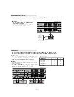
- Send the set’s audio to external audio equipment (stereo system) via the
Digital Audio Output (Optical) port.
Caution
: Do not look into the optical output port. Looking at the laser
beam may damage your vision.
Digital Audio Output
How to connect
1. Connect one end of an optical cable to the TV Digital Audio (Optical)
Output port.
2. Connect the other end of the optical cable to the digital audio (optical)
input on the audio equipment.
3. Set the “
TV Speaker
option -
Off
” in the AUDIO menu. Refer to page
23.
See the external audio equipment instruction manual for operation.
REMOTE
CONTROL
DVI
INPUT
COMPONENT 1
INPUT
OUTPUT
DVI INPUT
(PC/DTV)
RGB INPU
(PC/DTV)
GRADE
ORT
AUDIO INPUT
DIGITAL AUDIO (OPTICAL)
< Back panel of the set >
- The set has a special signal output capability which allows you to hook up a sec-
ond TV or monitor.
Connect the second TV or monitor to the set’s MONITOR OUTPUT. See the
Operating Manual of the second TV or monitor for further details regarding that
device’s input settings.
Note:
DTV, Component, RGB-PC/RGB-DTV, DVI-PC/DVI-DTV input sources cannot
be used for Monitor out.
Monitor Out Setup
S-VIDEO
MONITOR
OUTPUT
A/V
INPUT 1
Antenna
ANALOG/DT
AUDIO INPUT
VIDEO INPUT
AUDIO
VIDEO
COMPONENT 2
DVD
DTV
INPUT
.
COMPONENT 1
R
L
R
L
S-VIDEO
IN
(R) AUDIO (L)
VIDEO
< Back panel of the set >
Содержание DT-60PY10
Страница 21: ... 21 1 4 DT 60PY10 Power Board Structure 1 2 3 AC IN ...
Страница 22: ... 22 1 2 3 PFC ...
Страница 23: ... 23 1 2 3 DC DC ...
Страница 31: ... 31 BLOCK DIAGRAM BLOCK DIAGRAM ...
Страница 44: ......
Страница 45: ......
Страница 46: ......
Страница 48: ...Dec 2004 Printed in Korea P NO 3828VD0193C ...


