


—23—
RE-
MARKS
LOCATION
NO.
PART NO.
DHA1260HL
DHA1260HR
DESCRIPTION
Q'TY
PERSET
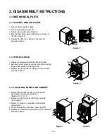
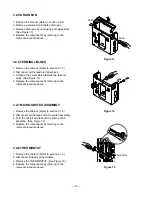
OUTER CASE PARTS
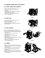
CONTROL PARTS
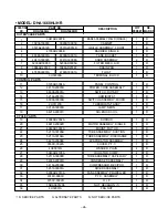
S: SERVICE PARTS A: ALTERNATE PARTS N: NOT SERVICE PARTS
6. REPLACEMENT PARTS LIST
• MODEL: DHA1260HL/HR
3041AD2007E
BASE ASSEMBLY WELD [SINGLE]
1
R
3090A10001E
3090A10001E
CABINET
1
R
3531A20012C
3531A20014D
GRILLE ASSEMBLY, FRONT
1
R
4790AD2003B
BARRIER, SINGLE
1
R
4838A10001A
4838A10001A
TANK, BUCKET
1
R
4941A30002A
4941A30008A
KNOB ASSEMBLY
2
R
5230AD3005A
5230AD3005A
FILTER MECH, AIR
1
R
3086AD2014C
3086AD2014F
DRAIN PAN
1
R
4768A30001A
4768A30001A
FLOAT
1
R
3H00390A
TERMINAL, BLOCK
1
R
3720AD3004A
PANEL, CONTROL
1
R
6411A20001B
6411A20001B
POWER CORD ASSEMBLY
1
R
6600A20001A
SWITCH, ROTARY
1
R
5216A20001A
HUMIDISTAT
1
R
6600A30003B
SWITCH ASSEMBLY, MICRO
1
R
2H01127F
THERMOSTAT ASSY
1
R
6912A30001B
LAMP, NEON
1
R
6421A90001C
SOLENOID COIL
1
R
4998AD2002A
SHROUD
1
R
4681A20002D
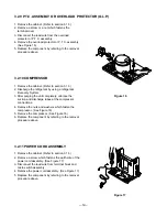
MOTOR ASSEMBLY, SINGLE
1
R
4960AD3003A
MOUNT, MOTOR
1
R
5211A30195A
TUBE ASSEMBLY, SUCTION
1
R
5211A30194A
TUBE ASSEMBLY, DISCHARGE
1
R
5421A20004D
EVAPORATOR ASSEMBLY
1
R
3550C-0021A
COVER, P.T.C.
1
R
4H00972G
WASHER, PLAIN
4
R
5040AR4195A
ISOLATOR, COMP.
4
R
5211A30008D
TUBE ASSEMBLY, CAPILLARY
1
R
5403A20001C
CONDENSER ASSEMBLY
1
R
5416A20009A
COMPRESSOR, RECIPRO
1
R
5851A30001A
DRIER ASSEMBLY
1
R
5900AD2013A
FAN ASSEMBLY, PROPELLER
1
R
6748C-0003C
P.T.C. ASSEMBLY
1
R
6750C-0005M
O.L.P.
1
R
1NHA0801206
NUT, HEXAGON (1)
4
R
4H02861A
FAN NUT
1
R
CYCLE PARTS
1
2
3
4
5
6
7
8
9
10
11
12
13
14
15
16
17
18
19
20
21
22
23
24
25
26
27
28
29
30
31
32
33
34
35
36
Содержание DHA1260HL
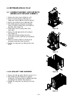
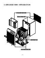
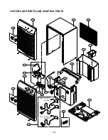
Страница 19: ...5 EXPLODED VIEW INTRODUCTION 19 OUTER CASE PARTS OUTER CASE PARTS CONTROL PARTS CYCLE PARTS ...
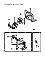
Страница 21: ... CYCLE PARTS AND CONTROL PARTS 21 21 20 32 36 19 30 33 18 35 34 25 26 27 ...
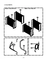
Страница 22: ... CYCLE PARTS 22 22 23 29 24 29 24 28 31 MODEL DHA1660HL HR MODEL DHA1260HL HR ...
Страница 25: ...P No 3828A30001W Printed in China ...


